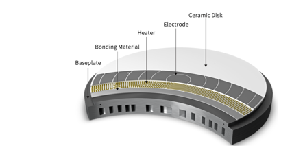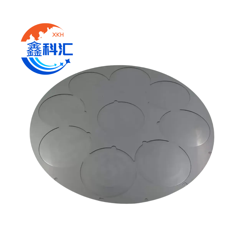
แผ่นเซรามิกอลูมินาที่มีรูหลายรูถูกใช้ในอุปกรณ์เซมิคอนดักเตอร์ ระบบกระจายก๊าซ อุปกรณ์สุญญากาศ ชุดฉนวนไฟฟ้า โครงยึดตัวกรอง ชิ้นส่วนเตาเผา และเครื่องจักรอุตสาหกรรมความแม่นยำสูง.
แม้โครงสร้างพื้นฐานอาจดูเรียบง่าย แต่การผลิตหลุมหลายร้อยหรือหลายพันหลุมที่จัดวางตำแหน่งอย่างแม่นยำบนแผ่นเซรามิก จำเป็นต้องมีการควบคุมอย่างละเอียดเกี่ยวกับเส้นผ่านศูนย์กลางของหลุม ระยะห่างระหว่างหลุม ตำแหน่งที่แท้จริง ความหนาของแผ่น ความเรียบ และคุณภาพของขอบ.
ความเปลี่ยนแปลงเล็กน้อยในเส้นผ่านศูนย์กลางของรูสามารถส่งผลต่อการไหลของก๊าซหรือการลดลงของความดันได้ ความผิดพลาดในระยะพิทช์ที่สะสมอาจทำให้แผ่นไม่สามารถจัดตำแหน่งให้ตรงกับชิ้นส่วนอื่นได้ ส่วนความแปรปรวนของความเรียบที่มากเกินไปอาจก่อให้เกิดช่องว่างในการปิดผนึกหรือการรับแรงกลที่ไม่สม่ำเสมอ.
ดังนั้น เอกสารขอเสนอราคา (RFQ) ที่ครบถ้วนควรกำหนดทั้งข้อกำหนดของรูแต่ละรูและประสิทธิภาพโดยรวมของแผ่นเซรามิกที่ผลิตเสร็จแล้ว.
ทำไมจึงใช้อลูมินาในการผลิตแผ่นที่มีหลายรู
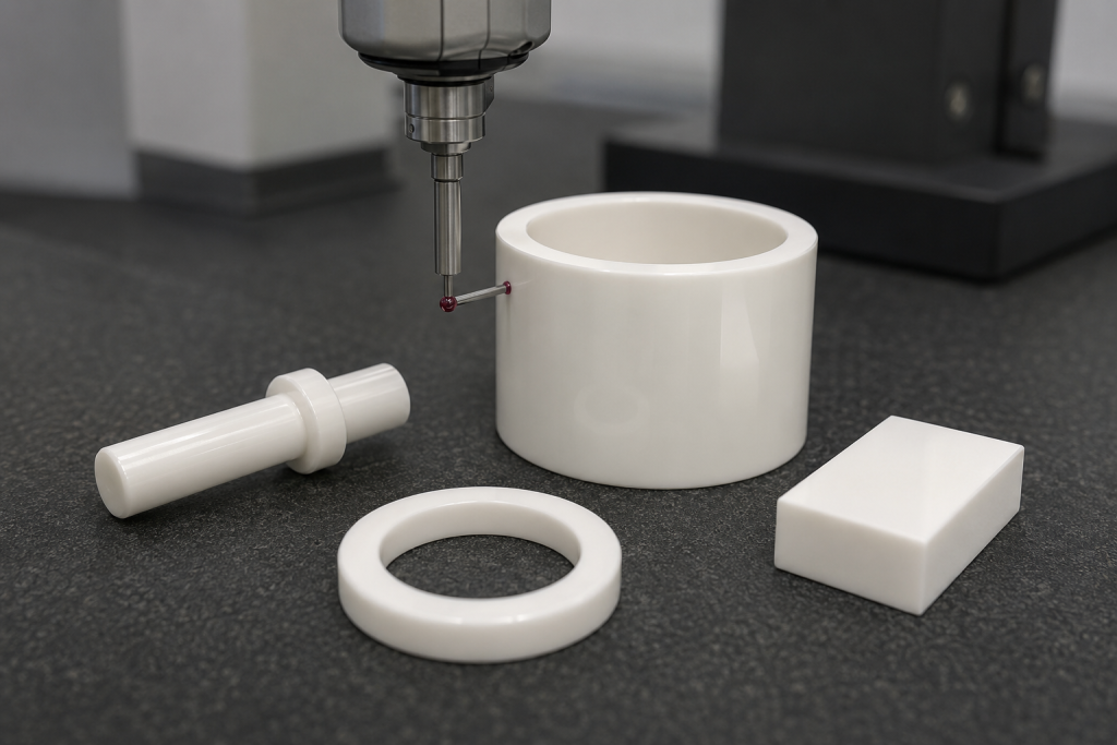
อะลูมินา (Alumina) หรือ Al₂O₃ เป็นหนึ่งในวัสดุเซรามิกขั้นสูงที่ได้รับการใช้งานอย่างแพร่หลายที่สุด โดยมันมีคุณสมบัติที่ผสมผสานกันอย่างเป็นประโยชน์ ได้แก่:
- ฉนวนไฟฟ้า
- ความแข็งสูง
- ความต้านทานการสึกหรอ
- ความแข็งแรงเชิงกล
- ความเสถียรในอุณหภูมิสูง
- ความต้านทานการกัดกร่อน
- ความเสถียรทางมิติ
- มีจำหน่ายในหลายระดับความบริสุทธิ์
- ความเข้ากันได้กับการเจียรแบบแม่นยำและการประมวลผลด้วยเลเซอร์
คุณสมบัติเหล่านี้ทำให้อลูมินาเหมาะสำหรับชิ้นส่วนที่ใช้ในสภาพแวดล้อมทางไฟฟ้า ความร้อน สูญญากาศ และเซมิคอนดักเตอร์ที่มีความต้องการสูง คุณสมบัติของเซรามิกอลูมินาและความแม่นยำในการกลึงที่สามารถทำได้ ขึ้นอยู่กับระดับคุณภาพ รูปทรง และกระบวนการผลิต. ข้อมูลเกี่ยวกับวัสดุอลูมินาของ Kyocera
ระดับความบริสุทธิ์ที่มักถูกกล่าวถึงสำหรับชิ้นส่วนอุตสาหกรรมและชิ้นส่วนเซมิคอนดักเตอร์ ได้แก่:
- อลูมินา 95%
- อลูมินา 96%
- อลูมินา 99%
- อลูมินา 99.5%
- 99.8% หรืออลูมินาที่มีความบริสุทธิ์สูงกว่า
ความบริสุทธิ์ที่สูงขึ้นไม่ได้หมายความโดยอัตโนมัติว่านั่นคือตัวเลือกที่ดีที่สุดสำหรับทุกการใช้งาน การเลือกวัสดุยังต้องพิจารณาถึงแรงกล คุณสมบัติไดอิเล็กทริก การสัมผัสกับสารเคมี อุณหภูมิ ความเรียบของพื้นผิว และค่าใช้จ่ายด้วย.
การใช้งานทั่วไป
แผ่นอลูมินาหลายรูที่ผลิตตามสั่งสามารถใช้ได้ในฐานะ:
- แผ่นกระจายก๊าซสำหรับเซมิคอนดักเตอร์
- แผ่นรองอาบน้ำเซรามิก
- แผ่นกระจายสุญญากาศ
- แผ่นฉนวนไฟฟ้า
- แผ่นรองรับเซรามิก
- อุปกรณ์ติดตั้งในเตาอุณหภูมิสูง
- ชิ้นส่วนสนับสนุนระบบกรอง
- แผ่นปรับทิศทางกระแส
- แผ่นติดตั้งเซ็นเซอร์
- ส่วนประกอบของอุปกรณ์พลาสมา
- อุปกรณ์สำหรับกระบวนการทางเคมี
- แผ่นปรับแนวความแม่นยำ
- แผ่นฉนวนหลายขา
- ส่วนประกอบของอุปกรณ์การประมวลผลเวเฟอร์
แอปพลิเคชันนี้จะกำหนดว่าคุณสมบัติที่สำคัญที่สุดคือความสม่ำเสมอของกระแส การฉนวนไฟฟ้า ความตรงตามขนาด ประสิทธิภาพของระบบสุญญากาศ ความแข็งแรงทางกล หรือความสะอาด.
ข้อมูลจำเพาะสำคัญที่ควรระบุในแบบวาด
| ข้อกำหนด | ข้อมูลเพื่อกำหนด |
|---|---|
| วัสดุ | ระดับและความบริสุทธิ์ของอลูมินา |
| ขนาดแผ่น | ความยาว ความกว้าง หรือเส้นผ่านศูนย์กลางด้านนอก |
| ความหนาของแผ่น | ความหนาตามค่าชื่อและค่าความคลาดเคลื่อน |
| เส้นผ่านศูนย์กลางของรู | เส้นผ่านศูนย์กลางตามชื่อเรียกและค่าความคลาดเคลื่อน |
| จำนวนรู | จำนวนรูทั้งหมด |
| ระยะห่างระหว่างรู | ระยะห่างระหว่างจุดศูนย์กลาง |
| รูปแบบรู | แบบสี่เหลี่ยม, แบบสลับ, แบบรัศมี หรือแบบกำหนดเอง |
| ตำแหน่งรู | ความคลาดเคลื่อนของตำแหน่งจริงเมื่อเทียบกับจุดอ้างอิง |
| รูปทรงของรู | ตรง, ค่อยๆ แคบลง, มีขั้น หรือมีร่องลึก |
| ระยะห่างจากขอบ | จากจุดกลางรูถึงขอบแผ่น |
| พื้นที่เปิด | พื้นที่รวมของรูเมื่อเทียบกับพื้นที่ของแผ่นที่ใช้งานได้ |
| ความเรียบ | ข้อกำหนดเกี่ยวกับความเรียบของพื้นผิวทั้งหมดหรือเฉพาะส่วน |
| การทำงานแบบขนาน | ความสัมพันธ์ระหว่างหน้าด้านหน้าและหน้าด้านหลัง |
| ผิวสำเร็จ | ผิวขัดหยาบ ผิวจัดแต่ง หรือผิวขัดเงา |
| คุณภาพของขอบรู | มุมตัด, รัศมี และพื้นที่สำหรับเศษโลหะ |
| ความสะอาด | ข้อกำหนดเกี่ยวกับการทำความสะอาดและการบรรจุหีบห่อ |
| การตรวจสอบ | การทดสอบมิติ การทดสอบทางสายตา การทดสอบความเรียบ และการทดสอบการไหล |
1. กำหนดหน้าที่ของรู
ก่อนที่จะเลือกขนาดเส้นผ่านศูนย์กลางของรู ให้กำหนดก่อนว่ารูเหล่านั้นมีหน้าที่อะไร.
อาจถูกออกแบบมาเพื่อ:
- แจกจ่ายก๊าซกระบวนการ
- สร้างการลดความดันที่ควบคุมได้
- สร้างพื้นที่เก็บรักษาแบบสุญญากาศ
- นำหมุดโลหะหรืออิเล็กโทรด
- จัดให้มีระบบแยกทางไฟฟ้า
- ลดน้ำหนักของชิ้นส่วน
- ให้สารเคมีไหลออก
- รองรับชั้นกรอง
- จัดให้ส่วนประกอบอื่นให้ตรงกัน
- ควบคุมอุณหภูมิหรือการไหลของอากาศ
รูปแบบรูที่ระบุไว้แบบเดียวกันอาจให้ประสิทธิภาพที่แตกต่างกันได้ ขึ้นอยู่กับความหนาของแผ่น ความหยาบของผนังรู รูปทรงของทางเข้า ความดัน ประเภทก๊าซ และออกแบบห้องด้านท้าย.
สำหรับการใช้งานกับก๊าซหรือระบบสุญญากาศ แบบวาดควรได้รับการสนับสนุนด้วยข้อมูลกระบวนการ แทนที่จะเป็นเพียงขนาดทางกลเท่านั้น.
2. เลือกขนาดเส้นผ่านศูนย์กลางของรู
เส้นผ่านศูนย์กลางของรูมีผลต่ออัตราการไหล ความแข็งแรง วิธีการผลิต และความยากในการตรวจสอบ.
เอกสารขอเสนอราคา (RFQ) ต้องกำหนดไว้ว่า:
- เส้นผ่านศูนย์กลางรูตามค่าที่ระบุ
- ความคลาดเคลื่อนของเส้นผ่านศูนย์กลาง
- สภาพรูผ่านหรือรูปิด
- ความลึกของรู
- ความเรียวสูงสุดที่อนุญาต
- รูปทรงทางเข้าและทางออก
- การตกแต่งพื้นผิวผนังแบบมีรู
- ความกลมหรือความทรงกระบอก ตามที่จำเป็น
- ความถี่ในการตรวจสอบ
รูเล็ก ๆ
รูที่มีเส้นผ่านศูนย์กลางเล็กอาจจำเป็นต้องใช้การเจาะด้วยเลเซอร์ เครื่องมือเพชรเฉพาะทาง การกลึงด้วยคลื่นอัลตราโซนิก หรือการขึ้นรูปก่อนการเผาผนึก.
Kyocera ระบุว่า การประมวลผลด้วยเลเซอร์ความแม่นยำสูงสามารถนำไปใช้กับวัสดุเซรามิกต่าง ๆ ได้โดยใช้ข้อมูล CAD ซึ่งสามารถเป็นประโยชน์สำหรับการผลิตต้นแบบและชิ้นส่วนในปริมาณน้อย โดยไม่จำเป็นต้องใช้แม่พิมพ์เฉพาะ. เทคโนโลยีการประมวลผลด้วยเลเซอร์เซรามิกของ Kyocera
อย่างไรก็ตาม ความแม่นยำของเส้นผ่านศูนย์กลาง ความเรียว และคุณภาพของขอบ ขึ้นอยู่กับ:
- ความหนาของแผ่น
- เส้นผ่านศูนย์กลางของรู
- อัตราส่วนความลึกต่อเส้นผ่านศูนย์กลาง
- ความบริสุทธิ์ของอลูมินา
- กระบวนการเลเซอร์หรือการกลึง
- สภาพพื้นผิวที่จำเป็น
- จำนวนรู
- ค่าขีดจำกัดของชั้นที่ได้รับผลกระทบจากความร้อนหรือชั้นที่หล่อใหม่
รูใหญ่
รูที่มีขนาดใหญ่กว่ามักตรวจสอบได้ง่ายกว่า แต่การจัดวางรูที่หนาแน่นอาจทำให้ความแข็งแรงทางกลของแผ่นลดลง.
การออกแบบควรมีวัสดุเซรามิกเพียงพอระหว่างรูที่อยู่ติดกัน และระหว่างรูกับขอบแผ่น.
ไม่มีค่าขั้นต่ำของสายยึดที่นำไปใช้ได้กับทุกแบบการออกแบบ ระยะห่างที่จำเป็นขึ้นอยู่กับเส้นผ่านศูนย์กลางของรู ความหนาของแผ่น วิธีรับแรง ระดับคุณภาพของวัสดุ และกระบวนการผลิต.
3. กำหนดระยะห่างระหว่างรูให้ถูกต้อง
ระยะห่างระหว่างหลุม คือระยะห่างจากจุดศูนย์กลางของหลุมหนึ่งถึงจุดศูนย์กลางของหลุมถัดไป.
สามารถกำหนดได้ใน:
- ทิศทาง X และ Y
- ทิศทางรัศมี
- ทิศทางตามแนวรอบวง
- แถวที่จัดเรียงแบบสลับ
- วงกลมที่อยู่ในวงกลมเดียวกัน
- ตารางพิกัด
- ข้อมูลแบบ CAD หรือแบบจำลอง 3D
รูปแบบของรูไม่ควรถูกกำหนดโดยขนาดระยะห่างระหว่างรูแต่ละรูเท่านั้น ความแตกต่างเล็กน้อยในระยะห่างระหว่างรูอาจสะสมตัวขึ้นเมื่อใช้กับแผ่นที่มีขนาดใหญ่.
การวาดภาพควรพิจารณาดังนี้:
- ระยะห่างระหว่างหลุมแต่ละหลุม
- ความสูงสะสมตามรูปแบบ
- ตำแหน่งที่แท้จริงของทุกหลุม
- ตำแหน่งของลายพิมพ์เมื่อเทียบกับขอบแผ่น
- ตำแหน่งของลายพิมพ์เมื่อเทียบกับรูติดตั้ง
- การหมุนของรูปแบบ
- ระบบอ้างอิงจุดอ้างอิง
ใช้ตำแหน่งจริงสำหรับรูปแบบที่ซับซ้อน
สำหรับแผ่นที่มีรูจำนวนมาก การกำหนดค่าความคลาดเคลื่อนของพิกัด ± แยกกันสำหรับแต่ละรู อาจทำให้การตีความแบบแปลนเป็นเรื่องยาก.
ข้อกำหนดเกี่ยวกับตำแหน่งจริง (true-position) ของ GD&T ที่สัมพันธ์กับจุดอ้างอิงการทำงาน (functional datums) สามารถช่วยให้ควบคุมรูปแบบทั้งหมดได้อย่างชัดเจนยิ่งขึ้น.
ระบบข้อมูลแบบทั่วไปอาจใช้:
- Datum A: หน้าติดตั้งหลัก
- Datum B: เส้นผ่านศูนย์กลางด้านนอกหรือขอบด้านข้าง
- Datum C: รูกำหนดตำแหน่ง, ขอบเรียบ หรือขอบรอง
หลังจากนั้น สามารถตรวจสอบรูปแบบรูได้โดยอ้างอิงจากจุดอ้างอิงเดียวกันที่ใช้ในการประกอบอุปกรณ์ขั้นสุดท้าย.
4. เลือกรูปแบบรู
รูปแบบแผ่นหลายรูที่นิยมใช้กัน ได้แก่:
ลายสี่เหลี่ยม
รูถูกจัดเรียงเป็นแถวแนวนอนและแนวตั้งที่เรียงตัวกัน.
ข้อดี ได้แก่:
- การกำหนดพิกัดอย่างง่าย
- การตรวจสอบด้วยตาเปล่าอย่างง่ายดาย
- โปรแกรมการกลึงที่เรียบง่าย
- การจัดตำแหน่งที่สะดวกกับชิ้นส่วนรูปสี่เหลี่ยม
รูปแบบเรียงสลับหรือรูปสามเหลี่ยม
แต่ละแถวถูกเลื่อนตำแหน่งจากแถวข้างต้น.
ข้อดีอาจรวมถึง:
- มีรูมากขึ้นภายในพื้นที่ที่ใช้งานได้
- การกระจายตัวในพื้นที่ที่สม่ำเสมอมากขึ้น
- ลักษณะการไหลที่แตกต่างกัน
- ลดจำนวนเส้นทางของสารที่ต่อเนื่องและไม่ถูกขัดจังหวะ
ลายรัศมี
รูถูกจัดวางตามวงกลมที่มีศูนย์กลางเดียวกันหรือตามเส้นรัศมี.
แบบนี้น่าจะมีประโยชน์สำหรับ:
- แผ่นกระจายก๊าซแบบวงกลม
- อุปกรณ์หมุน
- อุปกรณ์ยึดแบบสุญญากาศรูปวงกลม
- ส่วนประกอบของเตาหรือห้องเผา
ลายแบ่งเขต
พื้นที่ต่าง ๆ ใช้ขนาดเส้นผ่านศูนย์กลางของรู ระยะห่างระหว่างรู หรือความหนาแน่นที่แตกต่างกัน.
รูปแบบการจัดโซนอาจช่วยชดเชย:
- ความแตกต่างของการไหลจากกลางสู่ขอบ
- รูปทรงของห้อง
- ความเปลี่ยนแปลงของความดันในท้องถิ่น
- การกระจายตัวของอุณหภูมิ
- เขตสุญญากาศต่าง ๆ
การออกแบบตามโซนจำเป็นต้องระบุกลุ่มรูแต่ละกลุ่มให้ชัดเจน เพื่อป้องกันความผิดพลาดในการผลิตหรือการตรวจสอบ.
5. คำนวณพื้นที่เปิด
พื้นที่เปิด คืออัตราส่วนระหว่างพื้นที่รวมของรูกับพื้นที่ใช้งานได้ของแผ่น.
สำหรับแผ่นที่มีรูวงกลมที่เหมือนกันทุกจุด:
พื้นที่เปิด (%) = [N × π × d² ÷ 4A] × 100
สถานที่:
- N = จำนวนรู
- d = เส้นผ่านศูนย์กลางของรู
- A = พื้นที่แผ่นที่ใช้งานได้
พื้นที่เปิดมีประโยชน์ในการเปรียบเทียบการออกแบบรูปแบบรูต่าง ๆ แต่ไม่สามารถคาดการณ์ประสิทธิภาพการไหลได้อย่างครบถ้วน.
แผ่นสองแผ่นที่มีพื้นที่เปิดเท่ากันอาจให้ผลลัพธ์ที่แตกต่างกัน หากมีคุณสมบัติดังต่อไปนี้ที่แตกต่างกัน:
- เส้นผ่านศูนย์กลางของรู
- จำนวนรู
- ความหนาของแผ่น
- ความยาวของรู
- รูเรียว
- ความหยาบของผนังรู
- รูปทรงของขอบทางเข้าและทางออก
- ปริมาตรห้องส่วนต้น
สำหรับชิ้นส่วนที่การไหลเป็นปัจจัยสำคัญ อาจจำเป็นต้องทำการคำนวณ การจำลอง หรือการทดสอบการไหลของแบบต้นแบบ.
6. พิจารณาความหนาของแผ่นและอัตราส่วนระหว่างความกว้างกับความยาวของรู
ความหนาของแผ่นมีผลต่อความแข็ง ความเรียบ การผลิตรู และคุณสมบัติการไหล.
แผ่นที่หนากว่าอาจให้ประโยชน์ดังต่อไปนี้:
- ความแข็งต่อการโค้งที่สูงขึ้น
- ความทนทานต่อแรงกลที่ดีขึ้น
- ความลึกของเกลียวหรือความลึกของร่องเจาะให้กว้างขึ้น
- ความทนทานที่ดีขึ้นระหว่างการขนส่ง
อย่างไรก็ตาม การเพิ่มความหนา ก็ก่อให้เกิด:
- หลุมที่ลึกกว่า
- ความยากในการขุดเจาะที่เพิ่มขึ้น
- ความเสี่ยงที่เพิ่มขึ้นต่อการเกิดรูที่แคบลง
- การตรวจสอบภายในที่ยากขึ้น
- เวลาการกลึงเพิ่มขึ้น
- การลดลงของความดันที่มากขึ้นในระบบการไหล
- น้ำหนักของส่วนประกอบที่สูงขึ้น
ควรประเมินอัตราส่วนความลึกต่อเส้นผ่านศูนย์กลางของรูตั้งแต่ขั้นตอนต้นของการออกแบบ.
การผลิตรูที่มีเส้นผ่านศูนย์กลางเล็กบนแผ่นเหล็กหนาอาจยากกว่าการผลิตรูที่มีเส้นผ่านศูนย์กลางใหญ่บนแผ่นเหล็กบาง แม้ค่าความคลาดเคลื่อนของตำแหน่งรูจะเท่ากันก็ตาม.
7. การควบคุมความลาดเอียงของรูและรูปทรงทางเข้า
การเจาะเซรามิกและการประมวลผลด้วยเลเซอร์อาจก่อให้เกิดความแตกต่างระหว่างเส้นผ่านศูนย์กลางของจุดเข้าและจุดออก.
ในแบบวาดต้องระบุให้ชัดเจนว่าช่องนั้นต้องเป็น:
- ตรง
- มีรูปทรงเรียวเล็กน้อย
- รูปกรวย
- ขั้น
- เจาะรูให้ลึกกว่า
- มีมุมตัด
- มีมุมโค้ง
สำหรับแอปพลิเคชันที่มีอัตราการไหลสำคัญ ให้ระบุ:
- เส้นผ่านศูนย์กลางทางเข้า
- เส้นผ่านศูนย์กลางทางออก
- ความเรียวสูงสุด
- ความยาวรูที่มีประสิทธิภาพ
- มุมตัดหรือรัศมี
- อนุญาตให้ทำมุมโค้ง
สำหรับการจัดแนวหรือการใช้งานระบบนำทางด้วยพิน อาจจำเป็นต้องมีรูทรงกระบอกที่มีขนาดแคบกว่า.
8. ป้องกันการแตกของขอบรู
อะลูมินาเป็นวัสดุที่แข็งและทนต่อการสึกหรอ แต่ขอบที่ถูกเจาะหรือขัดให้เรียบในขนาดเล็กอาจเกิดการแตกหักได้ระหว่างกระบวนการผลิต การทำความสะอาด หรือการขนส่ง.
ข้อบกพร่องที่อาจเกิดขึ้น ได้แก่:
- ชิปที่ขอบทางเข้า
- การหลุดแนวต้าน
- รอยแตกแบบรัศมี
- หลุมบนพื้นผิว
- ความเสียหายที่ผนังบริเวณรู
- การเชื่อมต่อรอยแตกระหว่างรูที่อยู่ใกล้กัน
ภาพวาดควรกำหนด:
- ขนาดชิปสูงสุดที่อนุญาต
- ด้านวิกฤตและด้านไม่วิกฤต
- จำนวนชิปที่อนุญาต
- ระดับการขยายในการตรวจสอบ
- จำเป็นต้องทำมุมเอียงหรือไม่
- ขอบที่ได้รับการซ่อมแซมหรือปรับแต่งใหม่สามารถยอมรับได้หรือไม่
คำกำหนดเช่น “ไม่เกิดการแตก” ควรได้รับการสนับสนุนด้วยขีดจำกัดการยอมรับที่สามารถวัดได้.
9. กำหนดความเรียบและความขนาน
ความเรียบเป็นปัจจัยสำคัญอย่างยิ่งเมื่อใช้แผ่นนี้ในการปิดผนึก การกระจายสุญญากาศ การรองรับเวเฟอร์ หรือการติดตั้งแบบแม่นยำ.
ระดับความเรียบที่ต้องการควรระบุ:
- พื้นที่ที่วัดได้
- ความเรียบของพื้นผิวทั้งหมดหรือเฉพาะส่วน
- เขตขอบที่ถูกยกเว้น
- การวัดแบบอิสระหรือแบบถูกยึด
- อุณหภูมิอ้างอิง
- จุดตรวจสอบระหว่างการตรวจสอบ
- วิธีการตรวจสอบที่จำเป็น
ชิ้นส่วนเซรามิกขั้นสูงสามารถบรรลุระดับความเรียบและความละเอียดของพื้นผิวที่สูงมากได้ แต่ผลลัพธ์ที่สามารถบรรลุได้นั้นขึ้นอยู่กับขนาดและความหนาของแผ่น รวมถึงสภาพการรองรับและกระบวนการผลิต. ความสามารถด้านเซรามิกสำหรับอุตสาหกรรมเซมิคอนดักเตอร์ของ CeramTec
ความเรียบกับความขนาน
การปรับความเรียบจะควบคุมพื้นผิวหนึ่งอย่างอิสระ.
ความขนานกันกำหนดความสัมพันธ์ระหว่างพื้นผิวสองพื้นผิว.
แผ่นโลหะอาจผ่านเกณฑ์ความคลาดเคลื่อนของความหนา แต่ยังคงมีความแปรปรวนของความเรียบหรือความขนานที่มากเกินไป สำหรับการออกแบบที่มีความสำคัญสูง อาจจำเป็นต้องปฏิบัติตามทั้งสามข้อกำหนดดังต่อไปนี้:
- ค่าความคลาดเคลื่อนของความหนา
- ความเรียบของพื้นผิว
- การทำงานแบบขนานจากหน้าสู่หลัง
ความเรียบในสภาพถูกยึดเทียบกับสภาพอิสระ
แผ่นเซรามิกที่บางอาจมีพฤติกรรมต่างกันเมื่อวางไว้อย่างอิสระบนโต๊ะวัดผล และเมื่อถูกยึดด้วยสกรูเข้ากับอุปกรณ์.
หากชิ้นส่วนถูกติดตั้งด้วยสกรูหรือโครงสร้างกันน้ำ ให้ระบุว่าการรับมอบนั้นขึ้นอยู่กับ:
- ความเรียบของรัฐอิสระ
- ความเรียบภายใต้แรงจับที่กำหนด
- ประสิทธิภาพการปิดผนึกหลังการติดตั้ง
10. เลือกข้อกำหนดเกี่ยวกับพื้นผิว
พื้นผิวด้านหน้าและด้านหลังอาจมีรูปแบบดังต่อไปนี้:
- ในสภาพหลังการเผาผนึก
- พื้นผิว-พื้นดิน
- บดละเอียด
- ทับซ้อน
- ขัดเงา
การเคลือบผิวที่เหมาะสมขึ้นอยู่กับวัตถุประสงค์การใช้งาน.
| ฟังก์ชันพื้นผิว | ข้อกำหนดที่อาจมี |
| การติดตั้งทั่วไป | พื้นดิน |
| การปิดผนึกด้วยสุญญากาศ | บดละเอียดหรือขัดด้วยแผ่นขัด |
| จุดสัมผัสของเวเฟอร์ | ความหยาบและความสะอาดที่ได้รับการควบคุม |
| ฉนวนไฟฟ้า | การตกแต่งผิวตามการใช้งาน |
| ระบบแจกจ่ายก๊าซ | พื้นผิวที่สะอาดพร้อมขอบรูที่ได้รับการควบคุม |
| การสัมผัสแบบเลื่อน | บดละเอียดหรือขัดให้เรียบ |
| การติดด้วยกาว | พื้นผิวที่เตรียมไว้สำหรับกระบวนการติด |
อย่าระบุให้ทุกพื้นผิวมีผิวขัดเงา เว้นแต่จะจำเป็นทางด้านการใช้งาน การขัดเงาพื้นผิวขนาดใหญ่และพื้นที่รอบๆ รูหลายพันรูอาจทำให้ค่าใช้จ่ายเพิ่มขึ้นอย่างมาก.
11. เลือกวิธีการผลิต
วิธีการผลิตที่อาจใช้ได้ ได้แก่:
รูที่เกิดขึ้นก่อนการเผาผนึก
อาจเกิดรูระหว่างกระบวนการหล่อหรือการกลึงชิ้นงานที่ยังไม่แห้งสนิท.
ข้อดีอาจรวมถึง:
- ลดค่าใช้จ่ายในการกลึงหลังการเผาผนึก
- เหมาะสำหรับปริมาณการผลิตที่สูงขึ้น
- การผลิตแบบซ้ำอย่างมีประสิทธิภาพ
ข้อจำกัดอาจรวมถึง:
- ความแปรผันของการหดตัวจากการเผาผนึก
- ค่าความคลาดเคลื่อนของมิติที่กว้างขึ้น
- ความบิดเบี้ยวที่อาจเกิดขึ้น
- ค่าใช้จ่ายในการผลิตแม่พิมพ์สำหรับแบบผลิตภัณฑ์ที่ขึ้นรูป
การเจาะด้วยเลเซอร์
การประมวลผลด้วยเลเซอร์อาจเหมาะสำหรับ:
- แผ่นเซรามิกบาง
- รูเล็ก ๆ
- รูปแบบที่ซับซ้อน
- แบบต้นแบบ
- การผลิตในปริมาณน้อยหรือปานกลาง
ควรตรวจสอบกระบวนการนี้ในด้านความเรียว คุณภาพขอบ ผลกระทบทางความร้อน และสภาพผนังรูที่ต้องการ.
การกลึงเพชร
เครื่องมือเพชรสามารถใช้เพื่อ:
- รูที่ใหญ่กว่า
- เส้นผ่านศูนย์กลางพื้น
- รูเจาะขยาย
- คุณสมบัติการติดตั้ง
- ขนาดแผ่นความแม่นยำ
การประมวลผลแบบรวม
บางส่วนใช้การผสมผสานของ:
- การกลึงแบบมิตรต่อสิ่งแวดล้อมสำหรับรูปแบบรูหลัก
- การเผาผนึก
- การเจียรผิว
- การกลึงความแม่นยำของรูสำคัญ
- การขัดผิวหรือการขัดเงา
- การทำความสะอาดและการตรวจสอบครั้งสุดท้าย
กระบวนการที่ดีที่สุดขึ้นอยู่กับปริมาณ จำนวนรู ค่าความคลาดเคลื่อน และรูปทรงของแผ่น.
12. การตรวจสอบเส้นผ่านศูนย์กลางและตำแหน่งของรู
แผนการตรวจสอบที่เหมาะสมอาจรวมถึง:
| คุณสมบัติ | วิธีการตรวจสอบ |
| เส้นผ่านศูนย์กลางของรู | การวัดด้วยแสง ระบบการมองเห็น หรือเครื่องวัดพินแบบควบคุม |
| เส้นผ่านศูนย์กลางทางเข้าและทางออก | การวัดด้วยแสงจากทั้งสองด้าน |
| ระยะห่างระหว่างรู | การวัดวิสัยทัศน์ หรือ CMM |
| ตำแหน่งที่แท้จริง | CMM หรือระบบการมองเห็นที่ได้รับการปรับเทียบ |
| รูเรียว | การตัดชั้นด้วยแสง, CT หรือเครื่องวัดเฉพาะทาง |
| ความหนาของแผ่น | ไมโครมิเตอร์, เครื่องวัดความสูง หรือ CMM |
| ความเรียบ | CMM, แผ่นเรียบแบบออปติคัล หรือวิธีการวัดแบบอินเตอร์เฟอโรเมตริก |
| การทำงานแบบขนาน | CMM หรือการวัดความสูงแบบแม่นยำ |
| ความหยาบผิว | เครื่องวัดโปรไฟล์แบบสัมผัสหรือแบบแสง |
| ชิป Edge | การใช้กล้องจุลทรรศน์หรือการตรวจสอบด้วยตาเปล่าอย่างควบคุม |
| การอุดตันภายใน | การทดสอบด้วยแสง การทดสอบด้วยกระแสอากาศ หรือการทดสอบด้วยแรงดัน |
| ความสะอาด | การทดสอบแบบภาพ, แบบอนุภาค หรือตามข้อกำหนดของลูกค้า |
การสุ่มตัวอย่างเทียบกับการตรวจสอบตามมาตรฐาน 100%
สำหรับแผ่นที่มีรูหลายพันรู การวัดทุกมิติด้วยมืออาจไม่เป็นไปได้ในทางปฏิบัติ.
ตัวเลือกการตรวจสอบ ได้แก่:
- 100% ระบบตรวจสอบด้วยภาพอัตโนมัติ
- การเลือกตัวอย่างแบบตัวแทนตามเขต
- การตรวจสอบชิ้นแรกอย่างครบถ้วน
- การตรวจสอบเส้นผ่านศูนย์กลางจากทั้งสองด้าน
- การควบคุมกระบวนการทางสถิติ
- การทดสอบการไหลเต็มหรือการทดสอบความดัน
ในเอกสารขอเสนอราคา (RFQ) ต้องระบุระดับการตรวจสอบที่คาดการณ์ไว้ก่อนการเสนอราคา.
13. การทดสอบความไหลลื่นและการทำงาน
การตรวจสอบขนาดเพียงอย่างเดียวอาจไม่สามารถยืนยันได้ว่าระบบกระจายก๊าซหรือแผ่นสุญญากาศจะทำงานได้อย่างถูกต้อง.
การทดสอบการทำงานอาจรวมถึง:
- การวัดปริมาณการไหลของอากาศรวม
- การวัดการลดความดัน
- การเปรียบเทียบอัตราการไหลต่อหลุม
- การวัดอัตราการไหลตามเขต
- การทดสอบการรั่วของระบบสุญญากาศ
- การแสดงภาพการไหล
- การทดสอบการปิดผนึก
- การตรวจสอบความถูกต้องของกระบวนการทำความสะอาด
- การทดสอบอุปกรณ์ที่ติดตั้งแล้ว
สำหรับระบบที่มีความสำคัญสูง อาจมีการทดสอบแผ่นต้นแบบก่อนที่จะอนุมัติการผลิตในปริมาณจำนวนมาก.
14. ความสะอาดและบรรจุภัณฑ์
การใช้งานในอุตสาหกรรมเซมิคอนดักเตอร์และระบบสุญญากาศอาจจำเป็นต้องมี:
- อะลูมินาความบริสุทธิ์สูง
- ของเหลวสำหรับการกลึงที่ได้รับการควบคุม
- การทำความสะอาดด้วยคลื่นอัลตราโซนิก
- การล้างด้วยน้ำที่ผ่านกระบวนการกำจัดไอออน
- การอบแห้งในสภาพแวดล้อมที่สะอาด
- การบรรจุในถุงสองชั้น
- วัสดุที่เหมาะสำหรับห้องสะอาด
- การระบุล็อต
- บันทึกการตรวจสอบและทำความสะอาด
กระบวนการทำความสะอาดต้องสามารถกำจัดอนุภาคออกจากรูเล็กๆ ได้ แม้แผ่นโลหะจะดูสะอาดด้วยตาเปล่า แต่ภายในรูลึกอาจยังมีสารตกค้างติดอยู่.
บรรจุภัณฑ์ควรมีหน้าที่ป้องกัน:
- ขอบแผ่น
- ปากหลุม
- พื้นผิวขัดเงา
- ชิ้นตัดบาง
- คุณสมบัติการติดตั้ง
รายการตรวจสอบคำขอเสนอราคา (RFQ) สำหรับแผ่นอลูมินาหลายรู
โปรดให้ข้อมูลดังต่อไปนี้:
- ความบริสุทธิ์ของอลูมินา
- ความยาว ความกว้าง หรือเส้นผ่านศูนย์กลางด้านนอกของแผ่น
- ความหนาของแผ่น
- เส้นผ่านศูนย์กลางของรู
- ค่าความคลาดเคลื่อนของเส้นผ่านศูนย์กลางรู
- จำนวนรูทั้งหมด
- ระยะห่างระหว่างรู
- รูปแบบรู
- ค่าความคลาดเคลื่อนของตำแหน่งจริงของรู
- การออกแบบรูผ่านหรือรูปิด
- ความลาดเอียงสูงสุดของรู
- ข้อกำหนดเกี่ยวกับทางเข้าและทางออกของหลุม
- ระยะห่างขั้นต่ำระหว่างขอบ
- ข้อกำหนดเกี่ยวกับความเรียบ
- ข้อกำหนดเกี่ยวกับความขนาน
- ผิวสำเร็จ
- ค่าเผื่อเศษที่ขอบรู
- อุณหภูมิในการทำงาน
- สภาพก๊าซ สภาพสุญญากาศ หรือสภาพทางเคมี
- ข้อกำหนดเกี่ยวกับอัตราการไหลหรือความดัน
- ข้อกำหนดเกี่ยวกับการทำความสะอาดและการบรรจุหีบห่อ
- ข้อกำหนดเกี่ยวกับรายงานการตรวจสอบ
- จำนวนต้นแบบ
- ปริมาณการผลิตประจำปี
เมื่อรูปแบบรูมีความซับซ้อน ควรแนบแบบวาด 2D พร้อมด้วยแบบจำลอง 3D หรือไฟล์พิกัด.
ข้อผิดพลาดในการออกแบบที่พบบ่อย
ระบุเพียงขนาดเส้นผ่านศูนย์กลางของรูและจำนวนรูเท่านั้น
ความเอียง ตำแหน่งที่ถูกต้อง ความเรียว คุณภาพของขอบ และความหนาของแผ่น อาจมีความสำคัญเท่ากัน.
การไม่คำนึงถึงข้อผิดพลาดของมุมเอียงที่สะสม
ข้อผิดพลาดเล็กน้อยในตำแหน่งอาจสะสมตัวได้เมื่อมีกลุ่มรูขนาดใหญ่.
การทำให้เส้นผ่านศูนย์กลางของรูเล็กเกินไปเมื่อเทียบกับความหนาของแผ่น
อัตราส่วนความลึกต่อเส้นผ่านศูนย์กลางที่สูงจะทำให้การแปรรูปและการตรวจสอบมีความยากลำบากมากขึ้น.
การเจาะรูใกล้ขอบเกินไป
วัสดุที่ขอบไม่เพียงพออาจเพิ่มความเสี่ยงต่อการแตกร้าวและแตกเป็นชิ้นเล็กชิ้นน้อย.
การสับสนระหว่างความเรียบกับค่าความคลาดเคลื่อนของความหนา
แผ่นโลหะอาจตรงตามข้อกำหนดด้านความหนา แต่ยังคงไม่เหมาะสำหรับการปิดผนึก.
การใช้คำว่า “ไม่เกิดการแตก” โดยไม่มีขีดจำกัดที่วัดได้
กำหนดขนาดชิปสูงสุด ตำแหน่ง และระดับการขยายในการตรวจสอบ.
ต้องขัดให้ทุกพื้นผิวเป็นมันวาว
โดยทั่วไปแล้ว เฉพาะพื้นผิวที่สำคัญต่อการปิดผนึก การสัมผัส หรือความสะอาดเท่านั้น ที่จำเป็นต้องมีการขัดผิวให้ละเอียด.
การไม่ให้ความสำคัญกับการทดสอบการทำงาน
ประสิทธิภาพการกระจายการไหลไม่สามารถคาดการณ์ได้เสมอจากขนาดเพียงอย่างเดียว.
คำถามที่พบบ่อย
ความบริสุทธิ์ของอลูมินาควรเป็นเท่าใดสำหรับแผ่นหลายรูในอุตสาหกรรมเซมิคอนดักเตอร์?
การเลือกขึ้นอยู่กับขีดจำกัดการปนเปื้อน คุณสมบัติทางไฟฟ้า อุณหภูมิ การสัมผัสกับพลาสมาหรือสารเคมี และค่าใช้จ่าย โดยทั่วไปจะพิจารณาใช้อลูมินาที่มีความบริสุทธิ์สูงสำหรับงานที่มีความไวต่อการปนเปื้อนสูง.
รูสามารถมีขนาดเล็กได้เท่าใด?
เส้นผ่านศูนย์กลางขั้นต่ำของรูขึ้นอยู่กับความหนาของแผ่น ระดับคุณภาพของอะลูมินา จำนวนรู ค่าความคลาดเคลื่อน และวิธีการผลิต รูที่มีขนาดเล็กหรือลึกจำเป็นต้องมีการตรวจสอบกระบวนการผลิตอย่างละเอียด.
ควรกำหนดระยะห่างระหว่างรูด้วยค่า ± หรือด้วยตำแหน่งจริง?
แบบรูปที่เรียบง่ายอาจใช้ขนาดตามความสูง ส่วนแบบรูปที่ใหญ่หรือซับซ้อนมักดูชัดเจนขึ้นเมื่อควบคุมโดยใช้ตำแหน่งจริงที่สัมพันธ์กับจุดอ้างอิงเชิงฟังก์ชัน.
สามารถใช้เลเซอร์เจาะแผ่นอลูมินาที่มีหลายรูได้หรือไม่?
ใช่ครับ โดยเฉพาะอย่างยิ่งสำหรับแผ่นบาง รูขนาดเล็ก ลวดลายที่ซับซ้อน และแบบต้นแบบ ควรตรวจสอบความเรียวของรูและคุณภาพของขอบให้เหมาะสมกับแบบออกแบบเฉพาะนั้น.
วัดความเรียบของแผ่นอย่างไร?
วิธีการที่อาจใช้ได้ ได้แก่ การทำแผนที่ด้วย CMM การวัดความเรียบด้วยแสง และการตรวจสอบด้วยวิธีอินเตอร์เฟอโรเมตรี ควรกำหนดวิธีการรองรับแผ่นและพื้นที่ขอบที่ถูกยกเว้น.
อะไรเป็นสาเหตุที่ทำให้ความเร็วการไหลระหว่างรูต่างกัน?
ความแตกต่างอาจเกิดจากเส้นผ่านศูนย์กลางของรู ความลาดเอียง การอุดตัน ความหยาบของผนังรู ความหนาของแผ่น รูปทรงของขอบ และการกระจายแรงดันด้านต้น.
การตรวจสอบรู 100% เป็นสิ่งจำเป็นหรือไม่?
ขึ้นอยู่กับวัตถุประสงค์การใช้งานและจำนวนรู การตรวจสอบด้วยระบบออปติคัลอัตโนมัติหรือการทดสอบการทำงานของระบบอาจมีความเหมาะสมกว่าการวัดรูแต่ละรูด้วยมือ.
สามารถทำสำเนาแผ่นหลายรูที่เสียหายจากตัวอย่างที่มีอยู่ได้หรือไม่?
ตัวอย่างสามารถช่วยระบุโครงสร้างได้ แต่รูที่เกิดจากการสึกหรอ ความเสียหายที่ขอบ และการบิดเบี้ยวของแผ่นอาจส่งผลต่อการวัดผล นอกจากนี้ ยังควรตรวจสอบให้แน่ใจว่าส่วนต่อต่อของอุปกรณ์ต้นแบบและข้อกำหนดด้านการทำงานเป็นไปตามที่ระบุไว้.
สรุป
แผ่นเซรามิกอลูมินาที่มีรูหลายรูและเชื่อถือได้นั้น ต้องมีคุณสมบัติมากกว่าเพียงขนาดเส้นผ่านศูนย์กลางของรูตามที่กำหนดไว้เท่านั้น.
การออกแบบควรควบคุมระยะห่างระหว่างรู ตำแหน่งที่ถูกต้อง พื้นที่เปิด ความหนาของแผ่น ความเรียว คุณภาพของขอบรู ความเรียบ ความขนาน และความสะอาด นอกจากนี้ ข้อกำหนดในการตรวจสอบต้องสอดคล้องกับวัตถุประสงค์การใช้งานของชิ้นส่วนด้วย.
XKH Ceramics สามารถประเมินแบบวาดแผ่นอลูมินาหลายรูตามสั่ง สำหรับการใช้งานในอุตสาหกรรมเซมิคอนดักเตอร์ การแจกจ่ายก๊าซ ระบบสุญญากาศ การฉนวนไฟฟ้า และอุปกรณ์อุตสาหกรรม การให้ข้อมูลแบบรูที่ครบถ้วน ข้อกำหนดเกี่ยวกับความคลาดเคลื่อน และเงื่อนไขการทำงาน จะช่วยปรับปรุงความสามารถในการผลิต ความแม่นยำของใบเสนอราคา และความสม่ำเสมอในการผลิต.