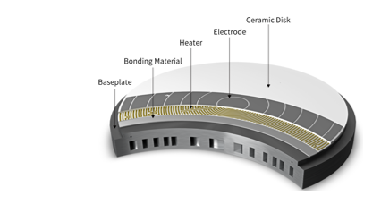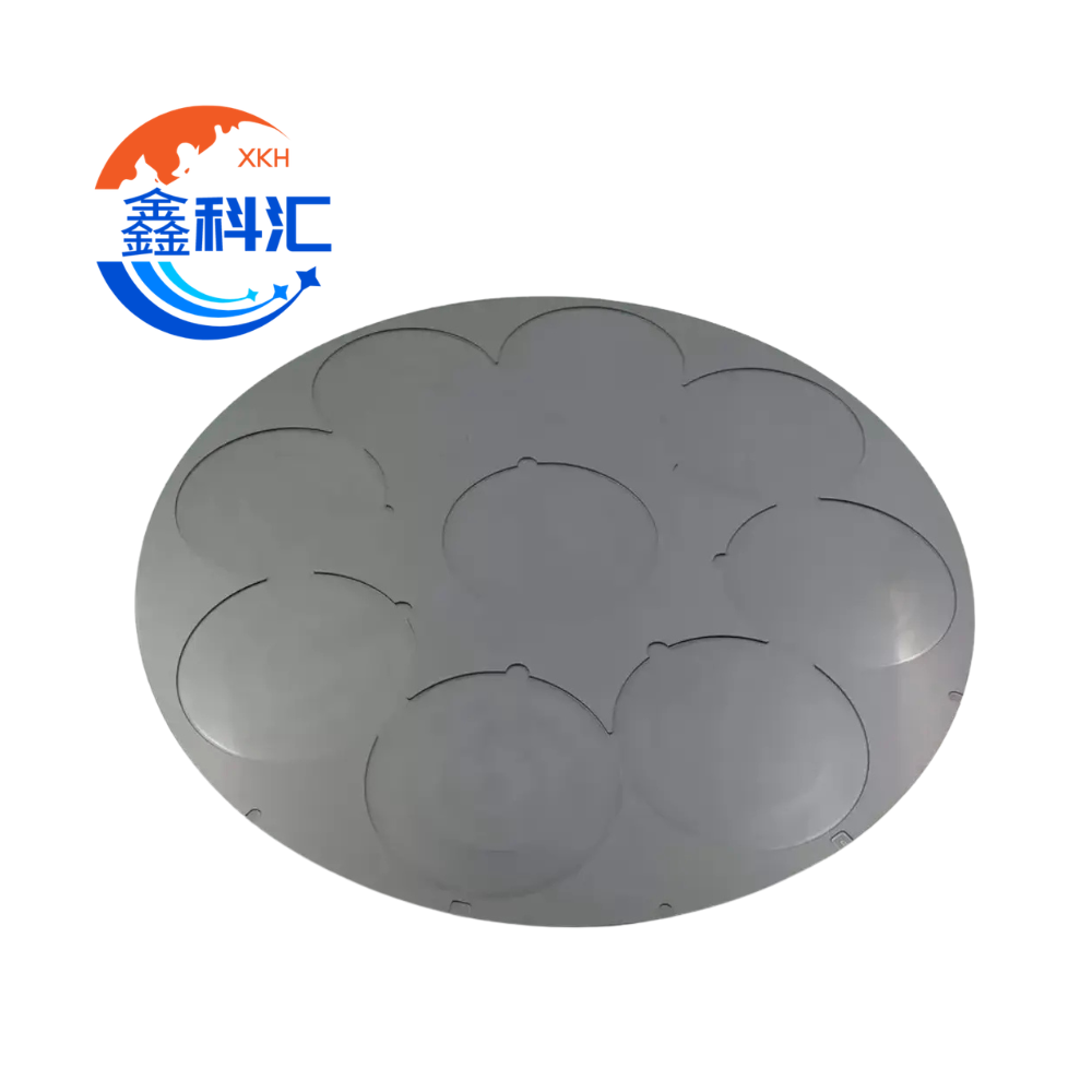
Alumina ceramic multi-hole plates are used in semiconductor equipment, gas distribution systems, vacuum fixtures, electrical insulation assemblies, filtration supports, furnace components and precision industrial machinery.
Although the basic structure may appear simple, manufacturing hundreds or thousands of accurately positioned holes in a ceramic plate requires careful control of hole diameter, pitch, true position, plate thickness, flatness and edge quality.
A small change in hole diameter can affect gas flow or pressure drop. Accumulated pitch error may prevent the plate from aligning with other components, while excessive flatness variation can create sealing gaps or uneven mechanical loading.
A complete RFQ should therefore define both the individual hole requirements and the overall performance of the finished ceramic plate.
Why Alumina Is Used for Multi-Hole Plates
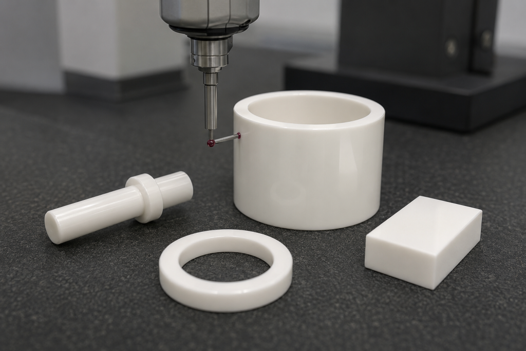
Alumina, or Al₂O₃, is one of the most widely used advanced ceramic materials. It offers a useful combination of:
- Elektrická izolace
- Vysoká tvrdost
- Odolnost proti opotřebení
- Mechanická pevnost
- Stabilita při vysokých teplotách
- Odolnost proti korozi
- Rozměrová stabilita
- Availability in different purity grades
- Compatibility with precision grinding and laser processing
These properties make alumina suitable for components used in demanding electrical, thermal, vacuum and semiconductor environments. Alumina ceramic properties and achievable machining precision depend on the grade, geometry and manufacturing process. Kyocera alumina material information
Common purity levels discussed for industrial and semiconductor components include:
- 95% alumina
- 96% alumina
- 99% alumina
- 99.5% alumina
- 99.8% or higher-purity alumina
Higher purity does not automatically mean that it is the best choice for every application. Material selection should also consider mechanical load, dielectric properties, chemical exposure, temperature, surface finish and cost.
Typické aplikace
Custom alumina multi-hole plates may be used as:
- Semiconductor gas distribution plates
- Ceramic shower plates
- Vacuum distribution plates
- Electrical insulation plates
- Ceramic support plates
- High-temperature furnace fixtures
- Filtration support components
- Flow straightening plates
- Sensor mounting plates
- Plasma equipment components
- Chemical processing fixtures
- Precision alignment plates
- Multi-pin insulating plates
- Wafer-processing equipment components
The application determines whether the most important feature is flow uniformity, electrical insulation, dimensional alignment, vacuum performance, mechanical strength or cleanliness.
Key Specifications to Include on the Drawing
| Specifikace | Information to define |
|---|---|
| Materiál | Alumina grade and purity |
| Plate dimensions | Length, width or outside diameter |
| Plate thickness | Nominal thickness and tolerance |
| Hole diameter | Nominal diameter and tolerance |
| Hole quantity | Total number of holes |
| Hole pitch | Center-to-center distance |
| Hole pattern | Square, staggered, radial or custom |
| Hole position | True-position tolerance relative to datums |
| Hole geometry | Straight, tapered, stepped or counterbored |
| Edge distance | Hole center to plate edge |
| Open area | Total hole area relative to active plate area |
| Flatness | Full-surface or local flatness requirement |
| Parallelism | Relationship between front and back faces |
| Povrchová úprava | Ground, lapped or polished |
| Hole-edge quality | Chamfer, radius and chip allowance |
| Cleanliness | Cleaning and packaging requirements |
| Inspection | Dimensional, visual, flatness and flow testing |
1. Define the Function of the Holes
Before selecting a hole diameter, determine what the holes are expected to do.
They may be designed to:
- Distribute process gas
- Generate a controlled pressure drop
- Create a vacuum holding area
- Guide metal pins or electrodes
- Provide electrical isolation
- Reduce component weight
- Allow chemical drainage
- Support a filtration layer
- Align another assembly
- Control heat or airflow
The same nominal hole pattern may perform differently depending on plate thickness, hole-wall roughness, inlet geometry, pressure, gas type and downstream chamber design.
For gas or vacuum applications, the drawing should be supported by process information rather than only mechanical dimensions.
2. Select the Hole Diameter
Hole diameter affects flow, strength, manufacturing method and inspection difficulty.
The RFQ should define:
- Nominal hole diameter
- Diameter tolerance
- Through-hole or blind-hole condition
- Hole depth
- Maximum allowable taper
- Entrance and exit geometry
- Hole-wall surface finish
- Roundness or cylindricity when required
- Inspection frequency
Small holes
Small-diameter holes may require laser drilling, specialized diamond tools, ultrasonic machining or forming before sintering.
Kyocera notes that high-precision laser processing can be applied to different ceramic materials using CAD data, which can be useful for prototypes and low-volume parts without dedicated molds. Kyocera ceramic laser processing technology
However, achievable diameter, taper and edge quality depend on:
- Plate thickness
- Hole diameter
- Depth-to-diameter ratio
- Alumina purity
- Laser or machining process
- Required surface condition
- Number of holes
- Heat-affected or recast-layer limits
Large holes
Larger holes are generally easier to inspect, but dense patterns can reduce the mechanical strength of the plate.
The design should maintain enough ceramic material between adjacent holes and between the holes and the plate edge.
There is no universal minimum ligament that applies to every design. Required spacing depends on hole diameter, plate thickness, loading method, material grade and manufacturing route.
3. Specify Hole Pitch Correctly
Hole pitch is the center-to-center distance between adjacent holes.
It may be defined in:
- X and Y directions
- Radial direction
- Circumferential direction
- Staggered rows
- Concentric circles
- A coordinate table
- CAD or 3D model data
A hole pattern should not be controlled only by individual pitch dimensions. Small pitch variations may accumulate across a large plate.
The drawing should consider:
- Individual hole-to-hole pitch
- Cumulative pitch across the pattern
- True position of every hole
- Pattern location relative to the plate edge
- Pattern location relative to mounting holes
- Rotation of the pattern
- Datum reference system
Use true position for complex patterns
For plates with many holes, defining each hole with separate ± coordinate tolerances can make the drawing difficult to interpret.
A GD&T true-position requirement relative to functional datums can provide clearer control of the complete pattern.
A typical datum system may use:
- Datum A: Primary mounting face
- Datum B: Outside diameter or side edge
- Datum C: Positioning hole, flat or secondary edge
The hole pattern can then be inspected relative to the same references used in the final equipment assembly.
4. Choose the Hole Pattern
Common multi-hole plate patterns include:
Square pattern
Holes are arranged in aligned horizontal and vertical rows.
Mezi výhody patří:
- Simple coordinate definition
- Easy visual inspection
- Straightforward machining program
- Convenient alignment with rectangular assemblies
Staggered or triangular pattern
Each row is offset from the previous row.
Advantages may include:
- More holes within a given active area
- More uniform spatial distribution
- Different flow characteristics
- Reduced uninterrupted solid paths
Radial pattern
Holes are positioned along concentric circles or radial lines.
This pattern may be useful for:
- Circular gas distribution plates
- Rotating equipment
- Round vacuum fixtures
- Furnace or chamber components
Zoned pattern
Different areas use different hole diameters, pitches or densities.
Zoned patterns may help compensate for:
- Center-to-edge flow differences
- Chamber geometry
- Local pressure variation
- Temperature distribution
- Different vacuum zones
Zoned designs require clear identification of every hole group to prevent manufacturing or inspection errors.
5. Calculate the Open Area
Open area is the ratio between the total hole area and the active area of the plate.
For a plate with identical circular holes:
Open area (%) = [N × π × d² ÷ 4A] × 100
Kde:
- N = number of holes
- d = hole diameter
- A = active plate area
Open area is useful for comparing different hole-pattern designs, but it does not fully predict flow performance.
Two plates with the same open area may produce different results if they have different:
- Hole diameters
- Hole quantities
- Plate thicknesses
- Hole lengths
- Hole taper
- Hole-wall roughness
- Inlet and outlet edge geometry
- Upstream chamber volume
For flow-critical components, calculation, simulation or prototype flow testing may be required.
6. Consider Plate Thickness and Hole Aspect Ratio
Plate thickness affects rigidity, flatness, hole processing and flow characteristics.
A thicker plate may provide:
- Greater bending stiffness
- Better resistance to mechanical loading
- More thread or counterbore depth
- Improved durability during handling
However, increasing thickness also creates:
- Deeper holes
- Greater drilling difficulty
- Higher risk of hole taper
- More difficult internal inspection
- Increased machining time
- Greater pressure drop in flow applications
- Higher component weight
The hole depth-to-diameter ratio should be evaluated early in the design.
A small-diameter hole through a thick plate may be more difficult to manufacture than a larger hole through a thin plate, even when the hole position tolerance is identical.
7. Control Hole Taper and Entrance Geometry
Ceramic drilling and laser processing may produce a difference between the entrance and exit diameters.
The drawing should state whether the hole must be:
- Straight
- Slightly tapered
- Conical
- Stepped
- Counterbored
- Chamfered
- Radiused
For critical flow applications, specify:
- Entrance diameter
- Exit diameter
- Maximum taper
- Effective hole length
- Chamfer or radius
- Allowed edge rounding
For alignment or pin-guide applications, a tighter cylindrical bore may be required.
8. Prevent Hole-Edge Chipping
Alumina is hard and wear-resistant, but small drilled or ground edges can chip during manufacturing, cleaning or handling.
Potential defects include:
- Entrance-edge chips
- Exit breakout
- Radial cracks
- Surface pits
- Hole-wall damage
- Connecting cracks between nearby holes
The drawing should define:
- Maximum allowed chip size
- Critical and non-critical faces
- Allowed number of chips
- Inspection magnification
- Whether chamfers are required
- Whether repaired or reworked edges are acceptable
Terms such as “no chipping” should be supported by measurable acceptance limits.
9. Specify Flatness and Parallelism
Flatness is especially important when the plate is used for sealing, vacuum distribution, wafer support or precision mounting.
The required flatness should identify:
- Measured surface
- Full-surface or local flatness
- Excluded edge zone
- Free-state or clamped measurement
- Reference temperature
- Support points during inspection
- Required inspection method
Advanced ceramic components can achieve very high levels of flatness and surface finish, but achievable results depend on plate size, thickness, support conditions and manufacturing process. CeramTec semiconductor ceramic capabilities
Flatness versus parallelism
Flatness controls one surface independently.
Parallelism controls the relationship between two surfaces.
A plate may satisfy its thickness tolerance while still having excessive flatness or parallelism variation. Critical designs may need all three requirements:
- Thickness tolerance
- Surface flatness
- Front-to-back parallelism
Clamped versus free-state flatness
A thin ceramic plate may behave differently when it is placed freely on a measurement table and when it is bolted into equipment.
If the component is mounted using screws or a sealing structure, specify whether acceptance is based on:
- Free-state flatness
- Flatness under defined clamping force
- Installed sealing performance
10. Select Surface Finish Requirements
The front and back surfaces may be supplied as:
- As-sintered
- Surface-ground
- Fine-ground
- Lapped
- Polished
The correct finish depends on the application.
| Surface function | Possible requirement |
| General mounting | Ground surface |
| Vacuum sealing | Fine-ground or lapped |
| Wafer contact | Controlled roughness and cleanliness |
| Elektrická izolace | Application-dependent finish |
| Gas distribution | Clean surface with controlled hole edges |
| Posuvný kontakt | Fine-ground or polished |
| Adhesive bonding | Surface prepared for bonding process |
Do not specify a polished finish on every surface unless it is functionally required. Polishing large surfaces and areas around thousands of holes can significantly increase cost.
11. Choose the Manufacturing Method
Possible manufacturing routes include:
Holes formed before sintering
Holes may be produced during molding or green machining.
Advantages may include:
- Lower post-sinter machining cost
- Suitable for higher volumes
- Efficient production of repeated patterns
Limitations may include:
- Sintering shrinkage variation
- Wider dimensional tolerances
- Possible deformation
- Tooling cost for molded designs
Laser drilling
Laser processing may be suitable for:
- Thin ceramic plates
- Small holes
- Complex patterns
- Prototypes
- Low- or medium-volume production
The process should be reviewed for taper, edge quality, thermal effects and required hole-wall condition.
Diamond machining
Diamond tools may be used for:
- Larger holes
- Ground diameters
- Counterbores
- Mounting features
- Precision plate dimensions
Combined processing
Some parts use a combination of:
- Green machining for the main hole pattern
- Sintering
- Broušení povrchu
- Precision machining of critical holes
- Lapping or polishing
- Cleaning and final inspection
The best process depends on quantity, hole count, tolerance and plate geometry.
12. Inspecting Hole Diameter and Position
A suitable inspection plan may include:
| Funkce | Inspection method |
| Hole diameter | Optical measurement, vision system or controlled pin gauge |
| Entrance and exit diameter | Optical measurement from both faces |
| Hole pitch | Vision measurement or CMM |
| True position | CMM or calibrated vision system |
| Hole taper | Optical section, CT or specialized gauge |
| Plate thickness | Micrometer, height gauge or CMM |
| Flatness | CMM, optical flat or interferometric method |
| Parallelism | CMM or precision height measurement |
| Drsnost povrchu | Contact or optical profilometer |
| Edge chips | Microscope or controlled visual inspection |
| Internal blockage | Optical, airflow or pressure test |
| Cleanliness | Visual, particle or customer-specified test |
Sampling versus 100% inspection
For a plate containing thousands of holes, measuring every dimension manually may be impractical.
Inspection options include:
- 100% automated vision inspection
- Representative sampling by zone
- First-piece complete inspection
- Diameter inspection from both surfaces
- Statistical process control
- Full flow or pressure testing
The RFQ should specify the expected inspection level before quotation.
13. Flow and Functional Testing
Dimensional inspection alone may not confirm that a gas distribution or vacuum plate will work correctly.
Functional testing may include:
- Total airflow measurement
- Pressure-drop measurement
- Per-hole flow comparison
- Zoned flow measurement
- Vacuum leakage testing
- Flow visualization
- Sealing test
- Cleaning validation
- Installed equipment trial
For highly critical systems, a prototype plate may be tested before production quantities are approved.
14. Cleanliness and Packaging
Semiconductor and vacuum applications may require:
- High-purity alumina
- Controlled machining fluids
- Ultrasonic cleaning
- Deionized-water rinsing
- Drying under clean conditions
- Double-bag packaging
- Cleanroom-compatible materials
- Lot identification
- Inspection and cleaning records
The cleaning process must remove particles from small holes. A plate may appear visually clean while still containing trapped residue inside deep holes.
Packaging should protect:
- Plate edges
- Hole entrances
- Leštěné povrchy
- Thin sections
- Mounting features
Alumina Multi-Hole Plate RFQ Checklist
Provide the following information:
- Alumina purity
- Plate length, width or outside diameter
- Plate thickness
- Hole diameter
- Hole diameter tolerance
- Total hole quantity
- Hole pitch
- Hole pattern
- Hole true-position tolerance
- Through-hole or blind-hole design
- Maximum hole taper
- Hole entrance and exit requirements
- Minimum edge distance
- Flatness requirement
- Parallelism requirement
- Povrchová úprava
- Hole-edge chip allowance
- Provozní teplota
- Gas, vacuum or chemical conditions
- Flow or pressure requirements
- Cleaning and packaging requirements
- Inspection report requirements
- Prototype quantity
- Annual production quantity
A 2D drawing should be accompanied by a 3D model or coordinate file when the hole pattern is complex.
Common Design Mistakes
Specifying only hole diameter and quantity
Pitch, true position, taper, edge quality and plate thickness may be equally important.
Ignoring cumulative pitch error
Small position errors can accumulate across a large hole array.
Making the hole diameter too small for the plate thickness
A high depth-to-diameter ratio increases processing and inspection difficulty.
Placing holes too close to the edge
Insufficient edge material can increase cracking and chipping risk.
Confusing flatness with thickness tolerance
A plate can meet thickness requirements but still be unsuitable for sealing.
Using “no chipping” without a measurable limit
Define maximum chip size, location and inspection magnification.
Requiring every surface to be polished
Only critical sealing, contact or cleanliness surfaces normally require a fine finish.
Ignoring functional testing
Flow-distribution performance cannot always be predicted from dimensions alone.
Často kladené otázky
What alumina purity should be used for a semiconductor multi-hole plate?
The choice depends on contamination limits, electrical properties, temperature, plasma or chemical exposure and cost. Higher-purity alumina is generally considered for more contamination-sensitive applications.
How small can the holes be?
Minimum hole diameter depends on plate thickness, alumina grade, hole quantity, tolerance and manufacturing method. Small or deep holes require a detailed manufacturing review.
Should hole pitch be controlled with ± dimensions or true position?
Simple patterns may use pitch dimensions. Large or complex patterns are often clearer when controlled using true position relative to functional datums.
Can alumina multi-hole plates be laser drilled?
Yes, especially for thin plates, small holes, complex patterns and prototypes. Hole taper and edge quality should be confirmed for the specific design.
How is plate flatness measured?
Possible methods include CMM mapping, optical-flat measurement and interferometric inspection. The plate support method and excluded edge zone should be defined.
What causes differences in flow between holes?
Differences may result from hole diameter, taper, blockage, hole-wall roughness, plate thickness, edge geometry and upstream pressure distribution.
Is 100% hole inspection necessary?
It depends on the application and hole quantity. Automated optical inspection or functional flow testing may be more practical than manual measurement of every hole.
Can a damaged multi-hole plate be copied from an existing sample?
A sample can help identify the structure, but worn holes, edge damage and plate deformation may affect measurements. Original equipment interfaces and functional requirements should also be confirmed.
Závěr
A reliable alumina ceramic multi-hole plate requires more than a specified hole diameter.
The design should control hole pitch, true position, open area, plate thickness, taper, hole-edge quality, flatness, parallelism and cleanliness. Inspection requirements must also match the functional purpose of the component.
XKH Ceramics can evaluate custom alumina multi-hole plate drawings for semiconductor, gas distribution, vacuum, electrical insulation and industrial equipment applications. Providing complete hole-pattern data, tolerance requirements and operating conditions helps improve manufacturability, quotation accuracy and production consistency.