A custom wafer boat must do more than hold a group of wafers. It must maintain consistent wafer spacing, fit the processing equipment, withstand repeated thermal cycles and avoid introducing particles or metallic contamination.
Small dimensional errors can create serious operating problems. Incorrect slot pitch may interfere with robotic loading, insufficient clearance can damage wafer edges, and excessive deformation may cause wafers to lean or contact each other during high-temperature processing.
For this reason, a reliable wafer boat RFQ should define the wafer, process, equipment interface, slot geometry, capacity, material, dimensional tolerances and inspection requirements.
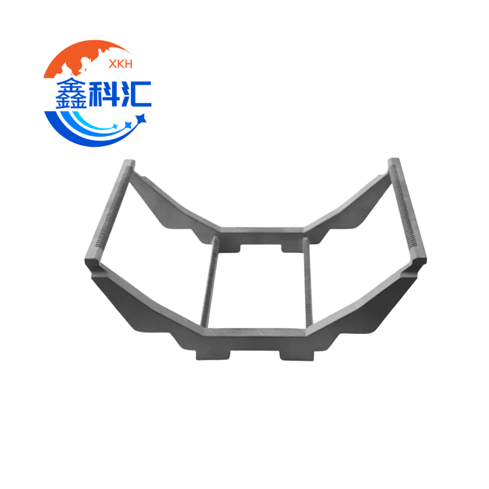
What Is a Semiconductor Wafer Boat?
A wafer boat is a precision carrier used to hold multiple semiconductor wafers during processes such as:
- Oxidação térmica
- Difusão
- LPCVD
- Recozimento
- High-temperature furnace processing
- Cleaning and chemical treatment
- Wafer storage and transfer
- Photovoltaic cell processing
Wafer boats may be installed in horizontal or vertical furnace systems. Their geometry must match the wafer loading direction, furnace tube, pedestal, paddle, robot and other handling components.
Semiconductor-grade silicon carbide is commonly used for high-temperature wafer carriers because it combines strength, thermal stability and chemical resistance. Official semiconductor component guides also identify SiC wafer boats for diffusion and LPCVD processing, including vertical and horizontal carrier configurations. CoorsTek semiconductor furnace components
Key Information Required for a Custom Wafer Boat
| Specification item | Information to provide |
|---|---|
| Diâmetro da pastilha | 100 mm, 125 mm, 150 mm, 200 mm, 300 mm or custom |
| Espessura da pastilha | Nominal thickness and allowable variation |
| Wafer orientation | Flat, notch and loading direction |
| Process type | Diffusion, oxidation, LPCVD, annealing or other |
| Temperatura de funcionamento | Normal and maximum process temperature |
| Atmosphere | Vacuum, inert gas, oxygen, reactive gas or chemical exposure |
| Slot pitch | Center-to-center distance between adjacent slots |
| Capacity | Number of process, monitor and dummy wafers |
| Slot geometry | Width, depth, opening, contact position and entry profile |
| Boat configuration | Horizontal, vertical, cylindrical or frame structure |
| Material | Quartz, SiC, coated SiC or another ceramic |
| Equipment interface | Paddle, pedestal, robot, furnace tube and positioning features |
| Tolerances | Pitch, straightness, flatness, parallelism and overall dimensions |
| Limpeza | Purity, cleaning, packaging and contamination limits |
| Inspeção | Dimensional report, material certificate and qualification method |
1. Confirm Wafer Diameter and Geometry
The wafer diameter is the first parameter to confirm because it determines the basic size, slot length, support position and equipment envelope of the wafer boat.
Common semiconductor wafer diameters include 100 mm, 125 mm, 150 mm, 200 mm and 300 mm. Smaller 2-inch and 3-inch wafers are also used in research, compound semiconductor and specialty applications. SEMI specifications cover a range of standardized wafer sizes and related dimensional requirements. SEMI wafer standards information
The RFQ should specify more than the nominal diameter. It should also include:
- Actual wafer diameter tolerance
- Espessura da pastilha
- Maximum bow or warp when relevant
- Flat or notch geometry
- Edge profile
- Coated or uncoated wafer condition
- Front-side and back-side contact restrictions
A boat designed only around the nominal diameter may not provide enough clearance for wafer variation, coatings or thermal expansion.
Wafer contact position
The slot should support the wafer at a controlled edge area. Contact with the active device surface should be avoided whenever possible.
The designer should know:
- Which side of the wafer faces the process direction
- Whether edge exclusion must be maintained
- Whether the wafer can contact the slot at two or multiple points
- Whether the wafer is loaded manually or by robot
- Whether the wafer includes deposited films that may change edge dimensions
2. Define the Slot Pitch
Slot pitch is the center-to-center distance between two adjacent wafer slots. It directly affects capacity, gas flow, thermal uniformity, robotic access and the total length of the wafer boat.
A smaller pitch allows more wafers to fit into the same furnace zone. However, reducing the pitch too much may create several risks:
- Insufficient clearance between wafers
- Difficult robotic loading and unloading
- Greater sensitivity to wafer bow or lean
- Restricted process gas flow
- Increased risk of wafer-to-wafer contact
- Reduced accessibility for inspection and cleaning
A larger pitch provides more clearance but reduces capacity and may require a longer boat or process chamber.
Basic length relationship
The approximate active slot length can be estimated as:
Active slot length = (Number of slots − 1) × Slot pitch
Additional space must then be added for:
- Front and rear end margins
- Loading clearance
- Support structures
- Positioning features
- Dummy wafer locations
- Equipment interface components
The slot pitch should therefore be selected together with the furnace manufacturer, process engineer and automation team. It should not be copied directly from a different tool simply because the wafer diameter is the same.
3. Determine the Required Capacity
Wafer boat capacity is not always equal to the number of production wafers processed in one batch.
A complete capacity specification may include:
- Production wafer slots
- Monitor wafer slots
- Dummy wafer slots
- Buffer slots
- Empty separation positions
- Reserved positions for future processes
For example, a process may require 50 production wafers but also need monitor wafers at the front, center and rear of the load. Dummy wafers may be required to improve thermal or gas-flow uniformity.
The RFQ should clearly distinguish between:
- Total number of physical slots
- Maximum loading capacity
- Normal production capacity
- Number and position of dummy wafers
- Number and position of monitor wafers
Capacity versus rigidity
Increasing capacity normally increases the overall boat length and total loaded weight. This can affect:
- Sagging during high-temperature operation
- Support point requirements
- Robot or paddle load
- Thermal mass
- Heating and cooling time
- Mechanical vibration during transfer
A high-capacity boat may require reinforced rails, optimized support locations or a different cross-sectional structure.
4. Specify Slot Width, Depth and Entry Geometry
Slot geometry controls how easily the wafer enters the boat and how securely it remains positioned.
Important slot dimensions include:
- Slot opening width
- Internal slot width
- Slot depth
- Slot angle
- Root radius
- Entry chamfer
- Wafer support height
- Contact length
- Distance between opposing supports
The slot must be wide enough to accept the wafer under worst-case dimensional and thermal conditions. However, excessive clearance can allow wafers to tilt, vibrate or shift during handling.
Entry profile
A smooth lead-in geometry helps guide the wafer into the slot. Sharp corners or rough machined edges can increase the risk of:
- Wafer edge chipping
- Scratching
- Geração de partículas
- Robot loading failure
- Localized stress
All wafer-contacting edges should be finished according to the agreed drawing and surface requirements.
5. Select the Appropriate Wafer Boat Material
Material selection depends on process temperature, chemical atmosphere, contamination limits, mechanical load and cleaning method.
Barcos de pastilhas de quartzo
Quartz is commonly selected for processes requiring:
- High chemical purity
- Good thermal shock performance
- Baixa contaminação
- Visual transparency
- Compatibility with quartz furnace tubes
However, the design must consider deformation, devitrification, cleaning frequency and service conditions at elevated temperatures.
Silicon carbide wafer boats
SiC wafer boats are commonly used when the application requires:
- High-temperature mechanical strength
- Greater rigidity
- Resistance to wear and corrosion
- High wafer capacity
- Repeated thermal cycling
- Longer service life under demanding furnace conditions
Available options may include reaction-bonded SiC, silicon-impregnated SiC, sintered SiC or CVD-SiC-coated structures. Material grade should be selected according to purity, mechanical and process requirements. High-purity CVD SiC materials can reach purity levels above 99.999%, although the required grade depends on the actual process. CoorsTek CVD silicon carbide information
Material information to include in the RFQ
- Required ceramic or quartz grade
- Purity requirement
- Maximum allowable metallic impurities
- Coating requirement
- Acabamento da superfície
- Cleaning method
- Expected service temperature
- Process gas and chemical exposure
- Required material certificate
6. Define Dimensional Tolerances
A wafer boat drawing should separate critical functional tolerances from general manufacturing tolerances.
Important dimensions may include:
| Critical feature | Why it matters |
| Individual slot pitch | Controls wafer spacing |
| Cumulative pitch error | Controls the position of the final slot |
| Slot width | Affects wafer clearance and stability |
| Slot depth | Controls wafer support and insertion |
| Rail straightness | Prevents wafer position variation |
| Support flatness | Affects installation and stability |
| Paralelismo | Maintains alignment between support rails |
| Overall length | Determines equipment fit |
| Overall width or diameter | Determines furnace tube clearance |
| Positioning feature location | Controls robot and pedestal alignment |
| Concentricity or runout | Important for cylindrical or rotating assemblies |
Cumulative pitch error
Even when every individual slot is within tolerance, small errors can accumulate across a high-capacity boat.
For example, a minor pitch deviation repeated across dozens of slots may cause the final wafer position to differ significantly from the robot’s expected coordinate.
The drawing should therefore specify both:
- Individual slot-to-slot pitch tolerance
- Total cumulative pitch tolerance across the complete slot array
Avoid unnecessarily tight tolerances
Tighter tolerances increase machining difficulty, inspection time, manufacturing cost and delivery time.
The best specification is not the tightest possible tolerance. It is the tolerance required for reliable equipment operation.
Critical dimensions should be identified separately from non-functional dimensions so the manufacturer can focus process control and inspection resources where they matter most.
7. Consider Thermal Expansion and High-Temperature Deformation
Room-temperature inspection does not fully represent wafer boat behavior inside a furnace.
At operating temperature, the boat may experience:
- Expansão térmica
- Sagging
- Rail deformation
- Changes in slot clearance
- Stress around joints or transitions
- Uneven expansion caused by temperature gradients
The design review should consider:
- Temperatura máxima de funcionamento
- Heating and cooling rate
- Total loaded wafer weight
- Support point positions
- Horizontal or vertical installation
- Uniformidade da temperatura
- Material thermal expansion
- Number of expected thermal cycles
For demanding applications, prototype qualification or thermal cycling tests may be required before full production approval.
8. Define Surface Finish and Cleanliness
Wafer-contact and process-exposed surfaces require special attention.
The RFQ should state:
- Surface roughness requirement
- Machined, polished or coated condition
- Edge and corner treatment
- Cleaning specification
- Particle control requirement
- Limites de contaminação por metais
- Packaging method
- Cleanroom handling requirement
The completed wafer boat should be cleaned and packaged to prevent recontamination during storage and transportation.
Packaging may include:
- Clean polyethylene bags
- Embalagem em saco duplo
- Protective foam or custom fixtures
- Individual compartment packaging
- Cleanroom-compatible outer packaging
- Lot and inspection labels
9. Establish an Inspection Plan
A custom wafer boat should be inspected against an approved drawing before shipment.
Typical inspection items include:
- Overall dimensions
- Slot count
- Individual slot pitch
- Cumulative pitch
- Slot width and depth
- Retidão
- Planicidade
- Paralelismo
- Position of locating features
- Surface condition
- Edge condition
- Material and coating verification
Depending on the geometry, inspection may use:
- Coordinate measuring machines
- Optical measuring systems
- Custom gauges
- Height gauges
- Precision fixtures
- Surface roughness instruments
- Material analysis
- Visual inspection under controlled lighting
For replacement parts, a first-article inspection report can help confirm compatibility before batch production.
10. RFQ Checklist for a Custom Wafer Boat
To receive an accurate quotation, provide the following information:
- Wafer diameter and thickness
- Wafer flat or notch orientation
- Process type
- Equipment or furnace model
- Horizontal or vertical installation
- Normal and maximum temperature
- Process atmosphere and chemicals
- Required material and purity
- Number of production wafer slots
- Number of dummy and monitor wafer slots
- Slot pitch
- Slot width and depth
- Overall dimensional limitations
- Critical tolerances
- Surface finish and cleaning requirements
- Coating requirements
- Requisitos relativos aos relatórios de inspeção
- Expected order quantity
- Prototype and production schedule
- Existing drawing, sample or equipment interface information
If a complete drawing is unavailable, the supplier may begin with an existing wafer boat sample, furnace envelope drawing or interface measurements. However, all functional dimensions should be confirmed before production.
Common Wafer Boat Specification Mistakes
Specifying only the wafer diameter
Two boats for 200 mm wafers may have completely different pitch, capacity, slot geometry and equipment interfaces.
Ignoring dummy and monitor wafer positions
Total slot count must include every wafer position required by the process.
Controlling individual pitch but not cumulative pitch
Long slot arrays require control of both local and total positional error.
Copying dimensions from another furnace
Equipment clearance, robot coordinates and process zones may differ even when the wafer diameter is identical.
Selecting material based only on temperature
Chemical atmosphere, purity, cleaning method, loading weight and thermal cycling are also important.
Using tight tolerances on every dimension
Over-specification increases cost without necessarily improving process performance.
Perguntas mais frequentes
What information is most important when requesting a custom wafer boat?
The most important information includes wafer diameter, wafer thickness, process temperature, slot pitch, total capacity, boat material, equipment interface and critical tolerances.
How is wafer boat slot pitch selected?
Slot pitch is selected according to wafer thickness, wafer bow, robot access, gas flow, process uniformity, furnace length and required capacity. It should be confirmed for the specific processing equipment.
Is the number of slots the same as production capacity?
Not always. Some slots may be reserved for dummy wafers, monitor wafers or process separation. The RFQ should state both total slots and actual production capacity.
Should I choose quartz or silicon carbide?
Quartz may be preferred for purity, chemical compatibility and quartz furnace integration. SiC may be preferred for high-temperature strength, rigidity, wear resistance and high-capacity loading. The final selection depends on the process.
Can a wafer boat be manufactured from an existing sample?
An existing sample can be used for dimensional evaluation, but wear or deformation may affect measurement accuracy. Equipment interface information and critical dimensions should still be confirmed.
What tolerances should be included on the drawing?
Critical tolerances normally include slot pitch, cumulative pitch, slot width, slot depth, straightness, parallelism, overall dimensions and positioning features. Exact values should be determined by equipment and process requirements.
Can custom wafer boats support 300 mm wafers?
Yes, but the larger wafer diameter and total load require careful evaluation of rigidity, deformation, robot access, furnace clearance and support structure.
What inspection documents can be supplied?
Depending on the project, documentation may include a dimensional inspection report, material certificate, surface finish report, coating information, cleaning record and first-article inspection report.
Conclusão
A reliable custom wafer boat specification must connect wafer geometry, slot pitch, capacity, material, equipment interface and process conditions.
The most successful projects begin with a complete RFQ and a clear distinction between critical functional dimensions and general manufacturing dimensions. This allows the manufacturer to control wafer position, equipment compatibility, thermal performance and cleanliness while avoiding unnecessary cost.
XKH Ceramics can evaluate custom wafer boat requirements based on customer drawings, existing samples or equipment interface information. When submitting an inquiry, include the wafer size, slot pitch, capacity, material, operating temperature and required inspection documents for a more accurate technical review and quotation.