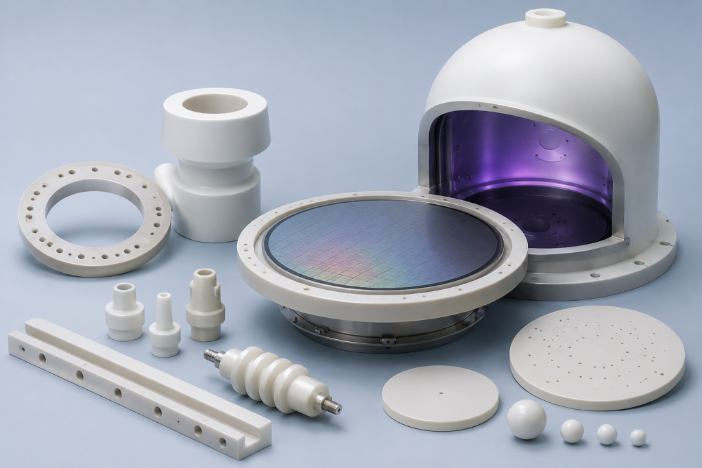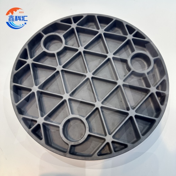
In semiconductor manufacturing, wafer handling components are often overlooked until they begin to affect yield, uptime or equipment stability. Among these components, the ceramic end effector plays a critical role in transporting wafers safely and repeatably between process stations.
As fabs continue to emphasize higher automation, lower particle generation and tighter dimensional control, the performance requirements for wafer handling end effectors are becoming more demanding. This is especially true for 200mm and 300mm wafer lines, where robotic handling must remain stable across thousands or even millions of cycles.
Ceramic end effectors are widely used because they offer a combination of rigidity, cleanliness, wear resistance and dimensional stability. However, not all ceramic end effectors are the same. Material choice, flatness, vacuum groove design, particle control and compatibility with the robot arm all directly influence handling reliability.
This article explains the key design and purchasing considerations for ceramic end effectors used in 200mm and 300mm wafer handling, with a particular focus on alumina and silicon carbide materials.

What Is a Ceramic End Effector?
A ceramic end effector is the wafer-contacting or wafer-supporting part mounted on a robotic handler, transfer arm or wafer transport mechanism. Its purpose is to pick up, support, transfer and place wafers with high positional accuracy and minimal contamination.
Depending on the equipment design, the end effector may be used in:
- atmospheric wafer handling
- vacuum transfer systems
- front-end module wafer transport
- load lock systems
- cleaning tools
- inspection systems
- lithography-related handling
- etch and deposition equipment
- furnace loading and unloading
In many systems, the end effector includes vacuum grooves, lift features, slots, edge-support structures or alignment surfaces to help hold the wafer securely during movement.
Why Ceramic Materials Are Used for Wafer End Effectors
Compared with plastics or common metals, advanced ceramics provide several advantages in semiconductor environments:
- high stiffness
- good dimensional stability
- low particle generation when properly finished
- high wear resistance
- resistance to process chemicals
- low outgassing
- thermal stability
- compatibility with cleanroom environments
These advantages make ceramics especially useful in wafer handling, where even small amounts of deformation or wear can affect repeatability and cleanliness.
However, the correct ceramic material depends on the actual application environment.
Why 200mm and 300mm Wafer Handling Requires Better End Effectors
Handling 200mm wafers already requires good stiffness and accuracy, but 300mm systems place significantly higher demands on the end effector.
There are several reasons for this.
First, the larger wafer diameter increases the importance of support geometry. Even a small deviation in flatness or support distribution can affect how the wafer sits on the end effector.
Second, 300mm automation systems are typically more sensitive to positioning accuracy, transfer repeatability and particle performance.
Third, thin wafers, processed wafers and patterned wafers can be more fragile than bare test wafers. In these cases, end effector design becomes part of the yield-protection strategy.
For these reasons, an end effector that is acceptable for a simpler 200mm handling application may not automatically be suitable for a 300mm automated platform.
Alumina vs SiC for Ceramic End Effectors
Two of the most common advanced ceramic materials for semiconductor end effectors are alumina and silicon carbide. Each has advantages, and the best choice depends on the balance between cost, rigidity, cleanliness and process requirements.
Alumina End Effectors
Alumina is one of the most widely used engineering ceramics in semiconductor equipment.
Advantages of Alumina
- good electrical insulation
- good wear resistance
- strong chemical resistance
- mature machining and fabrication process
- relatively lower cost compared with many advanced ceramics
- suitable for many cleanroom handling applications
Alumina end effectors are often selected when the application requires a reliable and cost-effective ceramic solution with good stability.
Limitations of Alumina
Compared with SiC, alumina usually has:
- lower stiffness
- lower thermal conductivity
- lower fracture toughness in some demanding mechanical designs
- potentially more limitations in ultra-thin or highly lightweight structures
For many standard wafer handling applications, these limitations are not critical. But for aggressive lightweight designs or applications requiring extremely high rigidity, SiC may offer better performance.
Silicon Carbide End Effectors
Silicon carbide is a high-performance ceramic widely used in semiconductor equipment because of its excellent rigidity, wear resistance and thermal behavior.
Advantages of SiC
- high stiffness
- high strength-to-weight potential
- good thermal stability
- excellent wear resistance
- low deformation under load
- suitable for lightweight precision structures
- good performance in demanding semiconductor environments
SiC is especially attractive when the end effector must remain thin and lightweight while still maintaining very high rigidity.
Limitations of SiC
- higher material and manufacturing cost
- more difficult machining
- tighter process control required during fabrication
- in some designs, cost may exceed what is necessary for the application
Therefore, SiC is not always the default best choice. It is often the best choice when performance requirements justify the additional cost.
When to Choose Alumina vs SiC
In practical terms, the selection often follows the application.
Alumina is often suitable for:
- standard atmospheric wafer handling
- general-purpose semiconductor robots
- applications with moderate mechanical load
- cost-sensitive but cleanroom-compatible systems
- electrically insulating designs
SiC is often preferred for:
- high-speed robotic transfer
- thin and lightweight end effector structures
- demanding 300mm wafer handling
- applications requiring higher rigidity
- environments where thermal stability is important
- high-end equipment demanding very low deformation
The decision should be based on the actual equipment conditions rather than on material reputation alone.
Flatness Is One of the Most Important Parameters
Flatness directly affects how a wafer sits on the end effector. Poor flatness can cause unstable support, vacuum inconsistency or wafer positioning errors.
For a wafer handling end effector, flatness matters because it influences:
- wafer support stability
- contact distribution
- vacuum holding behavior
- transfer repeatability
- alignment accuracy
- risk of local wafer stress
If the support plane is uneven, the wafer may experience tilt, rocking or uneven contact pressure. In severe cases, this can increase handling failure risk.
For 300mm wafer handling, flatness becomes even more important because the wafer diameter is larger and the process tolerances are often tighter.
Global Flatness vs Local Flatness
When evaluating an end effector, buyers should not look only at a single flatness value without understanding how it is defined.
Global flatness
Global flatness refers to the overall deviation across the entire wafer-supporting area.
Local flatness
Local flatness refers to smaller regions within the support area. This can be important when the wafer is supported at defined points, ribs or vacuum groove surfaces.
A part may have acceptable overall flatness but still contain local distortion that affects wafer support.
Therefore, for precision wafer handling, both global and local surface quality may need to be controlled.
Why Flatness Is Challenging in Ceramic End Effectors
Achieving good flatness in ceramics is not trivial. Several factors can influence the result:
- forming process
- sintering shrinkage
- material uniformity
- machining method
- grinding stress
- wall thickness design
- asymmetrical geometry
- slot and groove pattern
- post-processing quality
If the end effector contains complex vacuum grooves or a thin-arm structure, maintaining flatness becomes more difficult.
This is one reason why precision ceramic processing experience is very important for semiconductor equipment parts.
Vacuum Grooves: Why They Matter
Many wafer end effectors use vacuum to hold the wafer during transfer. In these designs, vacuum grooves help distribute suction beneath the wafer.
A good vacuum groove design should achieve several goals:
- sufficient holding force
- stable wafer retention during motion
- low contact area where appropriate
- minimal particle generation
- predictable vacuum response
- reduced risk of local wafer stress
Vacuum grooves are not just simple channels. Their geometry affects how the wafer is supported and how suction is distributed.
Key Vacuum Groove Design Considerations
When reviewing or designing vacuum grooves, the following factors are important:
Groove depth
If grooves are too shallow, airflow performance may be limited. If they are too deep, machining difficulty and structural weakness may increase.
Groove width
Groove width influences vacuum distribution and support area balance.
Groove layout
Radial, circular, grid or custom layouts may be used depending on wafer size and robotic motion requirements.
Support land area
The remaining contact or support surfaces between grooves must be designed carefully to support the wafer without causing excessive local stress.
Edge-region behavior
Vacuum performance near the wafer edge is often critical, especially during acceleration and deceleration of the robot arm.
Cleanability
Grooves must not create particle traps or cleaning difficulties.
Vacuum Grooves for 200mm vs 300mm Wafers
The groove pattern used for a 200mm wafer end effector may not be ideal for 300mm wafers.
A 300mm wafer usually requires more careful vacuum balancing because:
- the wafer area is larger
- the mass is higher
- the support behavior is more sensitive
- the risk of local deformation can be greater
- automation systems often demand tighter repeatability
Therefore, groove design should be matched to wafer diameter rather than copied blindly from smaller platforms.
Particle Control Is a Core Requirement
In semiconductor manufacturing, particle generation is one of the most important concerns for any wafer handling component.
A ceramic end effector may look dimensionally correct and still fail in actual use if it creates particles through wear, edge contact or unstable wafer handling.
Particle control is influenced by several factors:
- ceramic material quality
- sintering density
- surface finish
- machining quality
- edge rounding
- vacuum groove design
- contact pattern
- cleaning condition
- assembly quality
- robot motion stability
In practice, low-particle performance requires the complete design and manufacturing process to be controlled.
Where Particles Usually Come From
Typical particle sources in ceramic end effectors include:
- rough or damaged contact surfaces
- sharp groove edges
- micro-chipping at corners
- wear during repeated wafer contact
- contamination trapped in grooves
- improper cleaning after machining
- unstable wafer movement during pickup or placement
- misalignment with the robot arm or process station
This is why particle control should not be treated only as a material issue. It is also a structural, manufacturing and integration issue.
Surface Finish and Edge Quality
A semiconductor ceramic end effector should have appropriate surface quality on all wafer-contacting areas.
Important parameters may include:
- surface roughness
- polished or precision-ground finish
- absence of micro-chipping
- rounded or controlled edges
- clean vacuum groove walls
- low-defect contact surfaces
Sharp edges or poorly finished groove transitions can increase the risk of particles and wafer scratching.
For wafer handling, especially with patterned or sensitive wafers, surface finish is not just cosmetic. It directly affects reliability.
Lightweight Design vs Rigidity
A wafer handling robot often benefits from a lightweight end effector because lower mass can improve motion performance and reduce load on the actuator.
However, excessive lightweighting can reduce stiffness.
This creates a design tradeoff:
- lower weight helps speed and motion response
- higher stiffness helps stability and positioning accuracy
SiC is often selected when both low mass and high rigidity are required. Alumina may still be suitable when the design has enough thickness or when the motion requirements are less aggressive.
The correct design depends on robot speed, arm length, payload and wafer sensitivity.
Robot Compatibility: More Than Just Bolt Pattern
Many buyers focus first on the interface dimensions between the end effector and the robot arm. While that is important, true robot compatibility includes much more than mounting holes.
A ceramic end effector should be compatible with:
- robot arm structure
- mounting interface
- alignment datum
- vacuum connection
- load capacity
- motion profile
- acceleration and deceleration behavior
- sensor system
- equipment envelope
- collision-clearance requirements
Even if an end effector fits mechanically, it may not perform correctly if stiffness, vacuum behavior or center-of-gravity distribution is not compatible with the robot.
Center of Gravity and Dynamic Stability
For robotic wafer transfer, the center of gravity of the end effector is important.
If the weight distribution is poorly controlled, the robot may experience:
- vibration
- reduced positioning accuracy
- unstable high-speed motion
- increased wear on actuators
- difficulty during pickup and placement
This becomes especially important for larger or asymmetrical 300mm end effectors.
Therefore, the supplier should not only machine the part accurately, but also understand how geometry and material selection affect dynamic performance.
End Effector Design for Different Wafer Types
Not all wafers behave the same during handling. The end effector may need adjustment depending on the wafer category.
Examples include:
- bare wafers
- polished wafers
- patterned wafers
- thin wafers
- bonded wafers
- fragile research wafers
- wafers with backside films
- wafers after high-value process steps
A design that works for bare test wafers may not be ideal for thin or patterned product wafers.
This is why application details should be shared during RFQ whenever possible.
Thickness and Structural Design
The thickness of a ceramic end effector influences both rigidity and manufacturability.
A thicker structure may offer:
- better stiffness
- better fracture resistance
- easier dimensional stability
But it may also increase:
- mass
- robot load
- inertia
- response time
A thinner structure reduces weight, but makes flatness control and breakage resistance more challenging.
The optimum thickness depends on:
- wafer size
- material choice
- robot motion
- arm length
- support geometry
- vacuum groove design
- payload requirements
Ceramic Manufacturing Quality Matters
Two end effectors made from the same nominal material can perform very differently depending on manufacturing quality.
Important process factors include:
- powder purity
- forming consistency
- sintering control
- machining precision
- grinding quality
- surface finishing
- cleaning
- dimensional inspection
- flatness inspection
- vacuum path inspection
For semiconductor equipment parts, process stability at the supplier is often just as important as the material itself.
Inspection Items for Ceramic End Effectors
Typical inspection points may include:
- overall dimensions
- mounting dimensions
- flatness
- thickness tolerance
- slot and groove dimensions
- vacuum channel integrity
- surface roughness
- edge condition
- visual defects
- particle cleanliness
- material identification
- density or material grade verification if required
For higher-end projects, customers may also request:
- CMM measurement reports
- flatness maps
- vacuum leak tests
- particle-related validation
- trial assembly checks
Common Failure Risks in Wafer End Effectors
When a wafer end effector is poorly designed or poorly manufactured, several problems may occur:
- wafer slipping
- unstable vacuum pickup
- repeated particle generation
- wafer edge chipping
- robot alignment problems
- insufficient rigidity
- breakage during use
- inconsistent placement repeatability
- premature wear
- poor compatibility with automation systems
These failures can cause yield loss, downtime and expensive debugging inside the fab or tool builder environment.
Recommended RFQ Information
When sending an inquiry for a ceramic wafer handling end effector, it is better to provide more than just a drawing title.
A practical RFQ should include as much of the following as possible:
Basic application
- wafer size: 200mm or 300mm
- wafer type
- handling environment
- atmospheric or vacuum use
- process tool type
Material
- alumina or SiC preferred
- material grade if specified
- electrical insulation requirement if applicable
Structure
- overall dimensions
- thickness
- mounting interface
- support geometry
- vacuum groove design
- vacuum port location
Performance requirements
- flatness
- surface roughness
- allowable particle level
- stiffness requirement if applicable
- weight limitation
- vacuum performance requirement
Robot compatibility
- robot model or arm type
- mounting standard
- dynamic motion condition
- clearance limitations
- center-of-gravity concerns
Documentation
- dimensional inspection report
- material certificate
- cleaning requirement
- packing requirement
- sample quantity and production quantity
The more complete the RFQ, the easier it is for the supplier to recommend the correct material and process route.
Example Selection Logic
A customer may choose:
Alumina ceramic end effector when:
- 200mm handling is the main application
- the system requires good insulation
- cost is important
- the geometry is not extremely thin or lightweight
- a proven general-purpose ceramic solution is sufficient
SiC ceramic end effector when:
- 300mm wafer handling is involved
- higher stiffness is needed
- lower deformation is required
- a thinner and lighter design is preferred
- the robot runs at higher speed
- dynamic stability is more critical
Of course, the final decision should still be based on actual drawings and application conditions.
Conclusion
Ceramic end effectors are essential components in modern wafer handling systems, especially for 200mm and 300mm semiconductor manufacturing lines.
Choosing the right end effector involves more than selecting a ceramic material. Engineers and buyers must evaluate the complete combination of:
- alumina vs SiC
- flatness
- vacuum groove design
- particle control
- surface finish
- weight and rigidity
- robot compatibility
- manufacturing quality
Alumina remains a strong solution for many cleanroom wafer handling applications because it offers reliable performance and cost efficiency. Silicon carbide becomes especially attractive when higher stiffness, lighter structures and improved dynamic stability are required.
For semiconductor wafer handling, the best end effector is not simply the one made from the most advanced material. It is the one whose material, geometry, flatness, vacuum design and robot interface are properly matched to the wafer, tool and automation conditions.
A well-designed ceramic end effector can improve handling reliability, reduce particle risk and support long-term stable equipment operation.