Incoming inspection is an important control point when purchasing precision ceramic components for semiconductor equipment, electronics, automation, medical devices and other demanding industrial applications.
A ceramic component may appear acceptable at first sight while still containing dimensional deviations, edge chips, hidden cracks, incorrect hole positions, excessive warpage or surface defects that affect installation and service life.
Unlike ductile metal parts, advanced ceramics generally have limited tolerance for impact, bending and concentrated stress. A small chip near a mounting hole or a microcrack at a thin section can develop into a larger failure during assembly, thermal cycling or equipment operation.
For this reason, ceramic component inspection should not be limited to checking the quantity and overall dimensions. Buyers should define a complete incoming inspection plan covering:
- Document verification
- Lot identification
- Sampling method
- Critical, major and minor defects
- Boyutsal denetim
- Geometrical tolerances
- Surface condition
- Edge quality
- Material documentation
- Packaging condition
- Nonconforming product handling
This guide explains how purchasers can establish practical acceptance criteria for custom alumina, zirconia, aluminum nitride, silicon nitride, silicon carbide and other technical ceramic components.
Why Ceramic Incoming Inspection Requires a Defined Plan
Ceramic components are commonly manufactured through powder forming, sintering, grinding, lapping, polishing, laser machining and other finishing processes.
Variation may occur during:
- Powder preparation
- Forming
- Binder removal
- Sintering shrinkage
- Taşlama
- Drilling
- Parlatma
- Temizlik
- Ambalaj
- Transportation
Sintering shrinkage can make dimensional control more complex than machining a fully dense metal blank. Critical dimensions are therefore often produced or corrected by precision grinding after sintering.
Incoming inspection helps confirm that the supplier has delivered parts that meet the approved drawing, purchase specification and functional requirements.
A documented inspection process also helps prevent disputes caused by vague requirements such as:
- “No visible defects”
- “High precision”
- “Smooth surface”
- “No serious chipping”
- “Dimensions according to drawing”
These expressions are difficult to verify unless the inspection method and acceptance limits are defined.
Start with the Approved Drawing and Purchase Specification
Before opening the shipment, the inspector should identify the governing technical documents.
These normally include:
- Approved engineering drawing
- Drawing revision number
- Purchase order
- Material specification
- Supplier quotation
- Approved sample record
- Inspection standard
- Packaging requirement
- Certificate requirement
- Deviation approval, if applicable
The drawing revision is especially important. A dimensional report based on an old drawing may appear complete while failing to verify the latest customer requirements.
The incoming inspection record should clearly state which document revision was used.
Define the Inspection Lot
A sampling plan cannot be selected correctly until the inspection lot has been defined.
A lot should consist of parts produced under reasonably consistent conditions. Depending on the project, lot identification may consider:
- Purchase order number
- Part number
- Material batch
- Production batch
- Sintering batch
- Grinding batch
- Coating batch
- Cleaning batch
- Shipment date
Parts with different materials, drawing revisions or production histories should not automatically be combined into one inspection lot.
For high-value semiconductor ceramic components, buyers may require traceability to the raw material or sintering batch.
Selecting a Sampling Plan
Acceptance sampling allows the buyer to inspect a defined number of parts rather than inspecting every unit in a large shipment.
ISO 2859-1:2026 provides AQL-indexed single, double and multiple sampling schemes for lot-by-lot inspection by attributes. The 2026 edition replaced the earlier 1999 edition and added updated guidance, including skip-lot sampling provisions.
An attribute inspection records whether each inspected part is conforming or nonconforming rather than recording only a continuous measurement result.
Örnekler şunları içerir:
- Crack present or absent
- Chip exceeds limit or does not exceed limit
- Contamination present or absent
- Marking correct or incorrect
- Packaging damaged or undamaged
A complete sampling plan normally specifies:
- Lot size
- Inspection level
- Sample size
- Defect classification
- Acceptance Quality Limit
- Acceptance number
- Rejection number
- Normal, tightened or reduced inspection status
The purchaser and supplier should agree on the plan before production or shipment.
AQL Is Not the Same as an Allowed Defect Percentage
AQL is used to select a statistical sampling scheme. It should not be interpreted simply as a promise that a fixed percentage of defective parts is acceptable in every shipment.
The selected AQL should reflect:
- Product function
- Failure consequences
- Inspection cost
- Lot size
- Supplier performance
- Ability to replace rejected components
- Risk of equipment damage
- Risk of wafer or product contamination
Critical ceramic parts used in semiconductor processing may require stricter inspection than non-functional ceramic covers or spacers.
The actual sample size and acceptance criteria should be taken from the agreed standard or customer inspection procedure rather than estimated informally.
Classifying Ceramic Component Defects
A practical incoming inspection plan should divide defects into critical, major and minor categories.
Critical defects
A critical defect may create a safety risk, equipment failure, contamination event or immediate loss of function.
Examples may include:
- Through-cracks
- Incorrect material
- Part fracture
- Missing critical feature
- Severe contamination
- Incorrect part that can be assembled in an unsafe manner
- Electrical insulation failure
- Unapproved material substitution
Critical characteristics may require zero acceptance in the inspected sample or 100% inspection, depending on the application.
Major defects
A major defect can reduce function, installation compatibility, performance or service life.
Örnekler şunları içerir:
- Dimensional nonconformity
- Hole-position error
- Excessive flatness deviation
- Excessive warpage
- Large edge chip
- Surface damage in a sealing area
- Incorrect thread or insert position
- Unacceptable roughness
- Coating damage
- Improper packaging that risks component damage
Minor defects
A minor defect does not normally prevent use but may affect appearance or workmanship.
Örnekler şunları içerir:
- Small cosmetic mark outside the functional area
- Minor color variation
- Non-functional surface stain
- Small permissible edge imperfection
- Packaging label position variation
Defect classification should be based on function rather than appearance alone.
When 100% Inspection May Be Necessary
Sampling inspection is not suitable for every characteristic.
One hundred percent inspection may be appropriate for:
- Critical cracks
- Part identification
- Material mix prevention
- Safety-related features
- Critical mounting dimensions
- Very small production lots
- High-cost components
- First production batches
- Replacement parts for sensitive equipment
- Characteristics with a history of failure
However, 100% inspection does not automatically guarantee that every defect will be detected. Inspection effectiveness still depends on the method, equipment, inspector training and defect visibility.
Automated or fixture-based inspection may be needed when manual inspection cannot provide sufficient repeatability.
What Should Be Included in a Dimensional Inspection Report?
A dimensional report should provide traceable evidence that the inspected ceramic components conform to the approved drawing.
At minimum, the report should identify:
- Supplier name
- Customer name
- Part name
- Part number
- Drawing number
- Drawing revision
- Purchase order number
- Lot number
- Sample quantity
- Inspection date
- Inspector
- Ölçüm cihazları
- Equipment identification number
- Calibration status
- Nominal dimension
- Upper and lower limits
- Actual measured value
- Pass or fail result
- Remarks or approved deviations
A report that only states “OK” for every dimension provides less useful information than a report containing actual measured values.
Actual values allow the buyer to evaluate:
- Process centering
- Variation between parts
- Dimensions approaching a tolerance limit
- Consistency between shipments
- Potential tool wear
- Long-term supplier capability
Dimensional Characteristics Commonly Checked
The required dimensions depend on the ceramic component design, but incoming inspection may include the following.
Overall dimensions
- Length
- Width
- Height
- Thickness
- Outside diameter
- Inside diameter
Holes and slots
- Hole diameter
- Slot width
- Slot depth
- Hole pitch
- Hole position
- Countersink diameter
- Counterbore depth
- Distance from hole to edge
Geometrical characteristics
- Flatness
- Parallelism
- Perpendicularity
- Straightness
- Circularity
- Cylindricity
- Concentricity
- Position
- Runout
- Profile
ISO 1101:2017 defines the symbol language and interpretation rules used for geometrical product specifications, including form, orientation, location and runout controls.
The inspection report should use the same datum system and geometrical tolerance interpretation as the approved drawing.
For example, a hole position cannot be evaluated correctly without establishing the specified datums.
Do Not Replace GD&T with Simple Coordinate Measurements
A common inspection mistake is to measure two distances from a hole center to nearby edges and assume that this fully verifies the position tolerance.
This may not be equivalent to the geometrical position requirement shown on the drawing.
The inspector should understand:
- Datum reference frames
- Basic dimensions
- Material condition modifiers
- Pattern tolerances
- Common zones
- Profile requirements
- Runout references
When the part contains multiple precision holes or repeated feature patterns, the inspection method should verify the complete functional relationship between the features.
ISO 5458:2018 provides complementary rules for pattern specifications used with geometrical tolerancing requirements.
Measurement Equipment for Ceramic Components
Depending on the tolerance and geometry, inspection equipment may include:
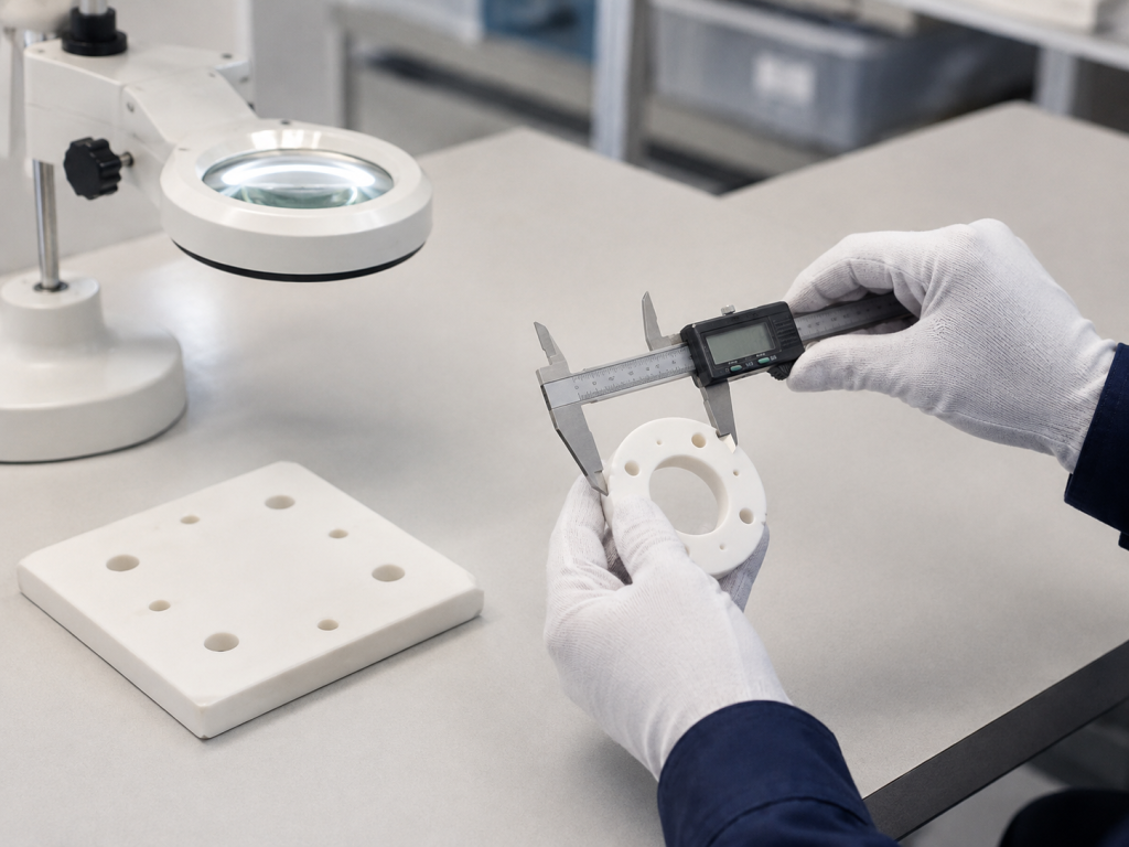
- Digital caliper
- Outside micrometer
- Height gauge
- Bore gauge
- Pin gauge
- Plug gauge
- Optical comparator
- Toolmaker’s microscope
- Coordinate measuring machine
- Vision measuring system
- Roundness tester
- Surface profilometer
- Flatness interferometer
- Granite surface plate
- Dial indicator
- Laser measuring system
The selected instrument should be appropriate for the tolerance.
A general rule is that measurement capability should be significantly better than the tolerance being verified. Extremely tight tolerances should not be accepted based only on a handheld caliper.
Ceramic surfaces can also be sensitive to concentrated contact. Measurement force, probe size and fixturing should not damage thin walls, polished faces or sharp edges.
Measurement Uncertainty and Acceptance Decisions
A measured value close to the tolerance limit requires careful evaluation.
ISO 14253-1:2017 establishes decision rules for verifying conformity or nonconformity while taking measurement uncertainty into account, including cases in which the measured result lies near a specification limit.
The buyer and supplier should agree on the decision rule when:
- Tolerances are very tight
- Measurement systems differ
- Parts are measured at different temperatures
- Results are close to the upper or lower limit
- The supplier and customer use different fixtures
- Surface form affects measurement repeatability
Without an agreed decision rule, the supplier may accept a part while the customer rejects the same part.
Temperature and Cleaning Before Measurement
Precision dimensions may be affected by temperature, contamination and fixturing.
Before inspection, ceramic components should generally be:
- Stabilized in the inspection environment
- Clean and dry
- Free from packaging particles
- Free from oil or fingerprints
- Supported without distortion
- Measured using the specified datum setup
The report should note special temperature requirements when tolerances are sufficiently tight for thermal effects to become relevant.
Surface Roughness Inspection
Surface roughness can affect:
- Sealing
- Friction
- Parçacık üretimi
- Vacuum performance
- Coating adhesion
- Electrical performance
- Optical performance
- Wafer contact
- Cleaning behavior
A surface requirement should specify more than a single roughness number.
Useful information includes:
- Roughness parameter
- Maximum permitted value
- Measurement direction
- Evaluation length
- Cutoff or nesting index
- Measurement location
- Number of measurements
- Contact or non-contact method
The ISO 21920 series provides the current framework for profile-based surface texture indication, parameters and specification operators. ISO 21920-1:2021 addresses drawing indications, ISO 21920-2:2021 defines terms and parameters, and ISO 21920-3:2021 covers specification operators.
Older drawings may reference withdrawn ISO 4287 terminology. ISO identifies ISO 21920-2:2021 as the replacement for ISO 4287:1997.
The supplier and buyer should confirm which surface texture standard governs the drawing.
Establishing Surface Defect Limits
“Free from defects” is usually too vague for an industrial ceramic specification.
The drawing or quality agreement should define:
- Defect type
- Maximum defect size
- Maximum quantity
- Inspection area
- Inspection magnification
- Lighting condition
- Functional surface classification
- Minimum spacing between defects
- Edge-zone requirements
Typical ceramic surface defects include:
- Cracks
- Chips
- Pits
- Pores
- Pinholes
- Scratches
- Grinding marks
- Polishing marks
- Stains
- Discoloration
- Inclusions
- Adhesive residue
- Embedded particles
- Uncleaned machining debris
Different limits may be applied to functional and non-functional surfaces.
Cracks
Cracks are generally more serious than cosmetic surface marks because they can propagate during assembly, vibration or thermal cycling.
The inspection requirement should distinguish between:
- Through-cracks
- Surface cracks
- Grinding cracks
- Edge cracks
- Radial cracks near holes
- Hairline indications
- Glaze or coating cracks, where applicable
For critical structural ceramic components, detectable cracks are commonly treated as unacceptable unless a specific engineering concession has been approved.
Visual inspection alone may not be sufficient for all crack types. Depending on material and risk, additional methods may include:
- Dye penetrant inspection
- Fluorescent penetrant inspection
- Microscopic inspection
- Ultrasonic inspection
- Acoustic inspection
- X-ray or computed tomography
The selected method must be compatible with the ceramic material, surface condition and cleanliness requirements.
Edge Chipping
Ceramic edges are vulnerable during machining, cleaning, handling and transportation.
An edge-chip requirement should define:
- Maximum chip length
- Maximum chip width
- Maximum chip depth
- Number of chips allowed
- Minimum spacing between chips
- Restricted zones
- Whether exposed sharp edges are permitted
A single maximum dimension may not be sufficient. A long, shallow chip and a short, deep chip can have different functional effects.
Special attention should be given to chips near:
- Mounting holes
- Thin sections
- Sealing surfaces
- Wafer-contact surfaces
- Vacuum channels
- Electrical isolation areas
- Sharp internal corners
The drawing should include an intentional chamfer or radius where a perfectly sharp edge is not functionally required. This can reduce accidental chipping and make acceptance criteria easier to control.
Pits and Pores
Some ceramic materials naturally contain a controlled level of porosity, while highly polished or vacuum-facing components may require much stricter surface limits.
Pore and pit acceptance should consider:
- Maximum opening diameter
- Maximum depth
- Quantity per inspection area
- Distance from functional edges
- Whether pores are open or closed
- Whether the surface will be coated
- Whether the component will be used in vacuum
- Whether trapped contamination can be removed
A visible pore that is harmless on an external cover may be unacceptable on a vacuum-sealing face or polished wafer-contact surface.
Scratches and Grinding Marks
Scratch limits should distinguish between cosmetic marks and functional damage.
Inspection criteria may define:
- Maximum scratch width
- Maximum scratch length
- Maximum quantity
- Allowed orientation
- Restricted inspection zones
- Whether the mark can be felt
- Whether it interrupts a sealing surface
- Whether it creates loose particles
Grinding marks may be acceptable when they are consistent with the specified manufacturing process and roughness requirement.
However, isolated deep grooves, torn surfaces or grinding burns may indicate improper processing.
Use Surface Zones
A practical drawing can divide the ceramic component into different inspection zones.
Zone A: Critical functional surface
Örnekler şunları içerir:
- Sealing surface
- Wafer-contact surface
- Vacuum surface
- Optical interface
- Precision mounting surface
- Electrical insulation surface
Zone A normally receives the strictest defect limits.
Zone B: Functional but non-critical surface
Örnekler şunları içerir:
- General mounting face
- Alignment surface
- Internal channel
- Equipment-facing surface
Moderate cosmetic defects may be permitted if they do not affect function.
Zone C: Non-functional surface
Örnekler şunları içerir:
- Hidden exterior surface
- Non-contact sidewall
- Identification area
Less restrictive visual requirements may be acceptable.
Zone-based requirements are usually clearer than applying one defect limit to the entire component.
Visual Inspection Conditions
Visual inspection should be performed under controlled and repeatable conditions.
The procedure may specify:
- Minimum illumination
- Light type
- Viewing distance
- Viewing angle
- Inspection time
- Magnification
- Background color
- Surface cleanliness
- Reference defect samples
Very high magnification should not be used unless the specification requires it. Otherwise, harmless features that are invisible under normal inspection conditions may be classified inconsistently.
Approved boundary samples or defect photographs can help inspectors and suppliers apply the same standard.
Material and Certificate Verification
Incoming inspection should also confirm that the delivered ceramic material matches the order.
Possible documents include:
- Certificate of conformance
- Material certificate
- Chemical composition report
- Density report
- Purity report
- Thermal conductivity data
- Electrical resistivity data
- Hardness data
- Coating certificate
- Raw material batch number
The required certificate should be identified before purchase.
A generic supplier datasheet is not always equivalent to a batch-specific inspection certificate.
For applications involving high-purity alumina, aluminum nitride or semiconductor-grade silicon carbide, the buyer may require batch traceability and specific impurity information.
Packaging Inspection
Ceramic parts can pass final inspection at the supplier and still be damaged during shipment.
Incoming inspection should check:
- Outer carton condition
- Internal cushioning
- Part-to-part contact
- Individual wrapping
- Cleanroom packaging
- Moisture protection
- Label accuracy
- Miktar
- Broken fragments inside the package
- Movement inside the container
- Vacuum packaging condition, if required
Precision ceramic components should not contact each other directly during transportation unless the packaging has been specifically designed for that arrangement.
A damaged carton or loose component should trigger a more detailed inspection.
What to Do When a Sample Fails
When a sampled component fails inspection, the buyer should follow the agreed sampling plan and nonconformance procedure.
Possible actions include:
- Rejecting the complete lot
- Moving to tightened inspection
- Performing 100% sorting
- Requesting supplier reinspection
- Returning the lot
- Accepting the lot under approved deviation
- Reworking the parts
- Replacing nonconforming components
- Opening a corrective action request
The supplier should not repair, grind, polish or rework a rejected ceramic component without approval when the change may affect dimensions, strength, cleanliness or traceability.
Recommended Incoming Inspection Workflow
A practical inspection sequence is:
Step 1: Verify documents
Confirm the purchase order, drawing revision, material and certificates.
Step 2: Inspect packaging
Look for impact, contamination, moisture and part-to-part contact.
Step 3: Confirm lot identity and quantity
Check labels, batch numbers, part numbers and shipment quantity.
Step 4: Select the sample
Use the agreed sampling standard and select parts randomly across the shipment.
Step 5: Perform visual inspection
Check cracks, chips, pits, scratches, contamination and workmanship.
Step 6: Measure critical dimensions
Use calibrated equipment and the drawing datum system.
Step 7: Verify surface requirements
Measure roughness, flatness, polish or coating condition where required.
Step 8: Review results
Compare actual measurements with limits using the agreed decision rule.
Step 9: Record nonconformities
Include photographs, defect locations and measured values.
Step 10: Accept, reject or escalate
Follow the agreed acceptance plan and supplier quality procedure.
Ceramic Component Incoming Inspection Checklist
Before approving a shipment, confirm:
- Correct part number
- Correct drawing revision
- Correct ceramic material
- Quantity matches the order
- Lot traceability is available
- Required certificates are included
- Packaging is undamaged
- No broken parts are present
- Sampling plan has been followed
- Critical defects are absent
- Dimensions meet drawing tolerances
- GD&T requirements are verified
- Flatness and parallelism are acceptable
- Hole dimensions and positions are acceptable
- Surface roughness meets the requirement
- Chips and cracks meet the defined limits
- Functional surfaces are clean
- Inspection equipment is calibrated
- Actual measurement values are recorded
- Deviations have written approval
Information to Include in a Ceramic Component RFQ
To reduce inspection disputes, buyers should provide the following when requesting a quotation:
- Ceramic material and grade
- Part drawing
- 2D and 3D files
- Drawing revision
- Kritik boyutlar
- Geometrical tolerances
- Yüzey pürüzlülüğü
- Functional surface zones
- Maximum chip limits
- Crack acceptance criteria
- Pore or pit limits
- Cleaning requirements
- Inspection sample size
- Required dimensional report
- Required certificates
- Packaging requirements
- Annual quantity
- Batch quantity
- Uygulama ortamı
When requirements are not yet fully defined, the supplier should be asked to review the drawing before quotation and identify dimensions that may be difficult to manufacture or inspect.
Sonuç
Incoming inspection of precision ceramic components should combine sampling control, dimensional verification, surface inspection, document review and packaging evaluation.
A reliable inspection plan should clearly define:
- How the lot is formed
- How samples are selected
- Which defects are critical
- Which dimensions require actual values
- How geometrical tolerances are measured
- What surface defects are acceptable
- Which decision rule applies near tolerance limits
- What happens when a sample fails
The most effective specifications avoid vague expressions and replace them with measurable limits, inspection zones and agreed methods.
For custom alumina, zirconia, aluminum nitride, silicon nitride and silicon carbide components, early agreement between the customer and supplier can reduce rejected shipments, measurement disputes and equipment installation problems.
Sıkça Sorulan Sorular
Should every ceramic component be inspected?
Not every dimension must be measured on every part. Sampling may be used for stable, non-critical characteristics. Critical cracks, material identity or safety-related characteristics may require 100% inspection.
What AQL should be used for ceramic components?
There is no single AQL suitable for every ceramic part. The level should be selected according to defect severity, application risk, lot size and supplier history. Critical characteristics normally require stricter control than cosmetic defects.
Is a supplier dimensional report enough for incoming acceptance?
A supplier report is useful, but the buyer may still verify selected critical dimensions and visual characteristics. The required level of verification depends on supplier qualification, component risk and previous quality performance.
How should ceramic edge chips be specified?
Define the maximum length, width and depth, the number permitted, restricted locations and the inspection method. A general statement such as “minor chips allowed” is not sufficiently clear.
Is “no visible crack” a complete crack specification?
Not always. The requirement should identify the inspection method, magnification and surface condition. High-risk components may require penetrant, microscopic or other non-destructive inspection.
Why can the supplier and customer obtain different dimensional results?
Differences may be caused by equipment, calibration, datum setup, fixturing, temperature, measurement force, surface condition and measurement uncertainty. The method and acceptance rule should be agreed before production.
Should actual measured values be included in the report?
For critical characteristics, actual values are strongly recommended. They provide more information about process variation and tolerance margin than a simple pass-or-fail statement.
Can cosmetic defects be accepted on non-functional surfaces?
Yes, provided the allowed defect type, size and quantity have been defined and the defect does not affect strength, cleanliness, installation or service performance.