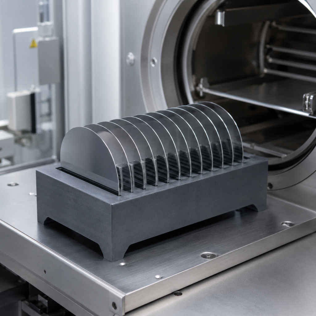
In semiconductor thermal processing, a wafer boat is more than a simple carrier. Its geometry influences wafer spacing, loading stability, gas flow, temperature distribution and particle performance throughout the process.
Silicon carbide wafer boats are commonly considered for diffusion, oxidation, annealing, LPCVD and other high-temperature semiconductor processes because silicon carbide offers excellent thermal stability, mechanical strength and resistance to chemical attack.
However, selecting the material alone is not enough. A reliable SiC wafer boat must be designed around the wafer size, process tube, loading system and actual thermal recipe. Slot pitch, wafer capacity, support geometry, dimensional tolerances and surface condition all need to work together.
This guide explains the main specifications engineers and purchasing teams should define when ordering a custom SiC wafer boat.
Why Use Silicon Carbide for Wafer Boats?
Wafer boats used in semiconductor furnaces experience repeated heating and cooling, reactive process gases, mechanical loading and strict contamination-control requirements. The carrier must maintain its geometry while minimizing its influence on the wafers and process environment.
Silicon carbide provides several useful characteristics:
- High mechanical strength at elevated temperatures
- Good dimensional stability during thermal cycling
- High thermal conductivity compared with many oxide ceramics
- Low thermal expansion
- Resistance to oxidation and chemical corrosion
- Good wear resistance
- Long service life under properly controlled conditions
- Compatibility with precision machining and engineered surface finishing
Different SiC material systems may be used depending on the application, including reaction-bonded SiC, recrystallized SiC, sintered SiC and CVD-coated SiC components.
The correct material grade should be selected according to process temperature, atmosphere, purity requirements, allowable porosity and expected service life.
1. Wafer Size and Boat Geometry
The first design input is the wafer diameter. SiC boats can be manufactured for different wafer formats, but every design must provide sufficient support without creating excessive contact with the wafer.
Important wafer information includes:
- Wafer diameter
- Wafer thickness
- Edge profile
- Notch or flat configuration
- Frontside and backside orientation
- Maximum allowable edge exclusion
- Whether the wafers are standard, thinned or unusually fragile
A boat designed for standard-thickness wafers may not safely hold thin or temporarily bonded wafers. Thin wafers are more sensitive to vibration, local contact stress and slot misalignment.
The boat geometry must also match the process equipment. The designer should confirm:
- Furnace tube inner diameter
- Usable hot-zone length
- Loading direction
- Paddle or cantilever dimensions
- Horizontal or vertical processing configuration
- Clearance between the boat and process tube
- Robot or manual loading method
Adequate clearance is necessary, but excessive open space can affect positioning and gas-flow behavior. The boat should remain stable during loading without contacting the process tube.
2. Slot Pitch
Slot pitch is the center-to-center distance between adjacent wafer slots. It directly affects wafer capacity, gas circulation and thermal interaction between neighboring wafers.
A smaller slot pitch increases the number of wafers that can fit into a given boat length. However, reducing the spacing too far may create several problems:
- Restricted gas flow between wafers
- Greater thermal shadowing
- Increased risk of wafer-to-wafer contact
- Reduced space for robotic loading
- Higher sensitivity to wafer bow or warp
- More difficult cleaning and inspection
A larger slot pitch improves separation and process-gas access but reduces batch capacity.
The appropriate pitch should therefore be determined from the process rather than selected only to maximize wafer quantity.
When specifying slot pitch, clearly define whether the dimension represents:
- Slot center-to-center distance
- Free space between wafer surfaces
- Distance between slot sidewalls
- Nominal pitch with an allowable accumulated error
Accumulated pitch error is particularly important on high-capacity boats. Even a small variation between individual slots can produce significant positional deviation across the full length of the carrier.
3. Slot Width and Wafer Clearance
Slot width must accommodate wafer thickness, thickness tolerance, thermal expansion and expected wafer deformation. It should also allow smooth loading and unloading.
If the slot is too narrow:
- Wafer edges may bind during loading
- Contact stress may increase
- Thermal expansion may cause sticking
- Edge chipping may occur
- Automated handling errors may increase
If the slot is too wide:
- Wafers may lean or move
- Orientation consistency may decrease
- Vibration during transport may increase
- Wafer position inside the hot zone may become less repeatable
Slot dimensions should be established using the maximum wafer thickness and expected bow or warp, not only the nominal wafer thickness.
The slot entrance may incorporate a controlled radius or chamfer to reduce the risk of edge damage. Sharp transitions and poorly finished corners should be avoided.
4. Wafer Support and Contact Geometry
The wafer should be supported securely while keeping the contact area as small and controlled as practical. The support geometry influences edge stress, particle generation and thermal behavior.
Typical design considerations include:
- Number of wafer contact points
- Contact position relative to the wafer edge
- Slot depth
- Support angle
- Contact radius
- Edge exclusion requirements
- Wafer insertion direction
A stable multi-point support arrangement helps prevent wafers from rocking or slipping. However, excessive contact can trap particles or create local thermal differences.
The contact surfaces should be smooth and free from sharp edges. Their geometry must also remain consistent across every slot.
For processes sensitive to backside contamination or slip formation, the relationship between contact position, wafer weight and thermal gradient should be evaluated carefully.
5. Wafer Capacity
Wafer capacity is determined by the usable boat length and selected slot pitch. Increasing capacity can improve throughput, but it also changes the thermal mass and gas-flow conditions inside the furnace.
A fully loaded boat may behave differently from a partially loaded one. The process team should evaluate:
- Maximum number of wafers per batch
- Standard production load
- Minimum qualified load
- Use of dummy wafers
- Empty-slot distribution
- Total loaded mass
- Required spacing at the front and rear of the boat
Dummy wafers may be placed near the ends of the load to improve process consistency, depending on the furnace and recipe. These positions should be included when calculating the required capacity.
The RFQ should distinguish between total slot count and the number of product wafers processed in each batch.
6. Thermal Uniformity
Although SiC has favorable thermal properties, the boat still affects heat transfer within the furnace. Cross-section thickness, support structures, wafer spacing and overall mass can influence heating and cooling rates.
A well-designed boat should avoid unnecessary differences in thermal mass along its length. Heavy local sections may heat and cool more slowly than thinner sections, contributing to temperature variation.
Factors affecting thermal uniformity include:
- Slot pitch
- Boat wall thickness
- Base and rail geometry
- Front-to-rear mass distribution
- Number of loaded wafers
- Distance from the heating elements
- Gas-flow direction
- Ramp and cooling rates
Thermal uniformity should be evaluated as part of the complete furnace system. The boat alone cannot correct an unsuitable hot zone or poorly optimized process recipe.
For demanding processes, thermal simulation or qualification runs may be necessary before finalizing the production design.
7. Gas Flow and Process Uniformity
The wafer boat should allow process gases to reach the wafer surfaces consistently. Solid sections, thick rails and overly dense wafer spacing can create flow resistance or local shadowing.
Designers should consider:
- Direction of process-gas flow
- Open area around and below the wafers
- Wafer-to-wafer spacing
- End effects at the first and last wafer positions
- Boat clearance inside the tube
- Interaction with baffles, injectors or liners
The best geometry depends on the specific process. Oxidation, annealing and deposition processes may have different gas-flow requirements.
If an existing boat has already been qualified, supplying a physical sample or complete drawing is usually safer than redesigning the carrier from limited dimensions.
8. Particle Control
Particle performance is one of the most important requirements for semiconductor wafer-handling components. Particles can originate from the SiC material, machining damage, coating defects, wafer contact or improper cleaning.
Important controls include:
Material Density and Porosity
Open porosity can retain process residue and cleaning chemicals. For contamination-sensitive applications, the selected SiC grade should provide the required density, purity and surface integrity.
Surface Roughness
Rough surfaces are more likely to retain particles and process deposits. However, unnecessarily polishing every surface may increase manufacturing cost without delivering a proportional process benefit.
Critical areas normally include:
- Wafer-contact surfaces
- Slot sidewalls
- Slot entrances
- Loading interfaces
- Surfaces exposed directly to the process environment
Edge Finishing
Sharp edges and machining burrs can become particle sources. Controlled chamfers and radii should be applied where appropriate, especially around slots and handling points.
Surface Damage
Grinding cracks, chipped corners and poorly blended tool marks can grow during repeated thermal cycles. Visual inspection alone may not reveal all subsurface damage, so the machining process must be controlled from the beginning.
Coating Integrity
If a CVD SiC coating is used, coating thickness, coverage, adhesion and defect limits should be defined. Pinholes, cracks, peeling and exposed substrate areas may affect purity and service life.
9. Dimensional Tolerances
A wafer boat contains many repeated features. Consistency between slots is therefore as important as the dimensions of an individual slot.
Typical inspection items include:
- Overall length, width and height
- Slot pitch
- Slot width and depth
- Slot parallelism
- Accumulated pitch error
- Rail straightness
- Base flatness
- Symmetry
- Wafer seating angle
- Position of locating features
- Interface dimensions for paddles or loading systems
Specifying unnecessarily tight tolerances across the entire part can increase cost and manufacturing time. Tolerances should be based on functional requirements.
Critical-to-function dimensions should be identified separately from general machining dimensions.
10. Cleaning and Packaging
A precisely machined SiC wafer boat can still become unsuitable for semiconductor use if it is cleaned or packaged incorrectly.
A typical controlled preparation process may include:
- Removal of machining residues
- Application-appropriate chemical cleaning
- High-purity water rinsing
- Controlled drying
- Final visual inspection
- Clean packaging
- Shock-protected shipment
The exact cleaning procedure must be compatible with the selected SiC grade and any coating applied to the surface.
Packaging should prevent:
- Slot damage
- Abrasion between components
- Recontamination after cleaning
- Moisture exposure
- Movement during international transportation
For complex or fragile boats, a dedicated support fixture may be preferable to standard foam packaging.
11. Inspection and Qualification
Before accepting a custom SiC wafer boat, the customer should establish clear inspection criteria.
Recommended inspection items include:
- Material grade verification
- Dimensional inspection report
- Slot-pitch measurement
- Wafer fit test
- Surface roughness measurement at designated areas
- Visual inspection for cracks and chips
- Cleanliness confirmation
- Coating inspection, when applicable
- Packaging inspection
- Reference wafer loading test
The first production lot may also require furnace qualification. This can include particle monitoring, wafer breakage evaluation, temperature-uniformity testing and comparison with the existing carrier.
Information Required for a SiC Wafer Boat RFQ
To receive an accurate quotation, provide the following information:
- Wafer diameter and thickness
- Wafer type and edge profile
- Total number of slots
- Required production-wafer capacity
- Slot pitch
- Slot width and depth
- Overall boat dimensions
- Horizontal or vertical configuration
- Furnace tube inner diameter
- Maximum operating temperature
- Process atmosphere and gases
- Preferred SiC grade
- Purity requirement
- Surface roughness requirement
- CVD SiC coating requirement
- Critical dimensional tolerances
- Cleaning and packaging standard
- Required inspection documents
- Drawing, sample or equipment interface information
- Estimated order quantity
When an existing design is being replaced, supplying both the drawing and a used or unused sample can reduce the risk of interface errors.
Conclusion
A SiC wafer boat must balance capacity, mechanical stability, thermal behavior, gas flow and particle control. Maximizing the number of slots without considering these interactions can lead to wafer damage, process nonuniformity or contamination.
The most important design parameters include wafer size, slot pitch, slot clearance, support geometry, accumulated pitch accuracy and surface condition. These specifications should be established together with the furnace configuration and process recipe.
For custom semiconductor applications, early communication between the equipment engineer, process team and ceramic manufacturer helps shorten qualification time and produce a wafer boat that performs reliably over repeated thermal cycles.
TAGS: SiC wafer boat, silicon carbide wafer boat, semiconductor wafer boat, wafer boat design, wafer boat slot pitch, wafer boat capacity, thermal uniformity, particle control, semiconductor ceramics, SiC ceramic carrier, wafer furnace boat, custom SiC components, semiconductor thermal