Advanced ceramic components are widely used in semiconductor equipment, vacuum systems, precision machinery, electrical insulation, chemical processing and high-temperature applications. Materials such as alumina, zirconia, aluminum nitride, silicon carbide and silicon nitride provide excellent hardness, wear resistance, corrosion resistance, electrical insulation and dimensional stability.
Despite these advantages, ceramic components can still fail.
Unlike most metals, technical ceramics usually undergo very little plastic deformation before fracture. A component may appear normal during operation and then crack or break suddenly. Small defects introduced during forming, sintering, machining, transportation or installation can gradually develop into serious failures under mechanical loading, temperature cycling, chemical exposure or repeated contact.
Ceramic failure analysis should therefore go beyond examining the final broken area. Engineers need to determine where the damage began, what caused the defect to grow and which material, design, manufacturing or operating factors contributed to the failure.
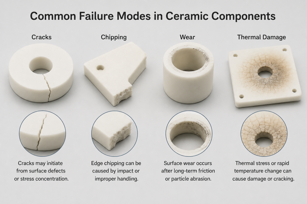
This article explains the main failure modes of advanced ceramic components, including cracking, edge chipping, surface wear, thermal shock, thermal cycling, chemical corrosion and plasma erosion.
Why Ceramic Components Fail
Ceramic component failure is rarely caused by a single factor. In many cases, several conditions act together.
Common causes include:
- Excessive tensile or bending stress
- Mechanical impact
- Sharp corners and stress concentrations
- Machining-induced microcracks
- Improper mounting or clamping
- Thermal shock
- Repeated heating and cooling
- Химическая атака
- Abrasive wear
- Plasma erosion
- Internal porosity
- Sintering defects
- Material contamination
- Poor dimensional fit
- Incorrect material selection
For example, a surface crack may be introduced during grinding. The defect may remain undetected during dimensional inspection. Repeated thermal cycling can then enlarge the crack until the component suddenly fractures.
A proper failure investigation must therefore consider the entire lifecycle of the part.
Characteristics of Ceramic Failure
Technical ceramics behave differently from ductile metals.
A metal part may bend, stretch or deform before complete failure. Ceramic materials, however, are generally brittle and more sensitive to local tensile stress.
Important characteristics include:
- High compressive strength
- Lower tensile strength
- Limited plastic deformation
- Sensitivity to surface defects
- Sensitivity to sharp corners
- Rapid crack propagation
- Strong dependence on surface finish
- Statistical variation in strength
The usable strength of a ceramic component is influenced not only by the basic material but also by the size and location of its largest defect.
1. Cracking in Ceramic Components
Cracking is one of the most serious and common ceramic failure modes.
Cracks may originate from:
- Grinding scratches
- Surface pits
- Internal pores
- Inclusions
- Острые внутренние углы
- Drilled holes
- Threads
- Thin-wall transitions
- Improper assembly
- Localized impact
- Термические градиенты
- Химическая коррозия
Surface cracks
Surface cracks are particularly dangerous because maximum tensile stress often occurs at or near the component surface.
Possible sources include:
- Coarse grinding
- Worn diamond tools
- Excessive machining pressure
- Insufficient coolant
- Metal contact
- Improper handling
- Aggressive cleaning
- Edge impact
Even a microscopic surface crack can significantly reduce mechanical strength.
Internal cracks
Internal cracks may develop during powder processing and sintering.
К возможным причинам относятся:
- Uneven powder compaction
- Binder-removal problems
- Density gradients
- Delamination between pressed layers
- Rapid heating during firing
- Uneven furnace temperature
- Large internal pores
Internal defects are more difficult to detect and may require advanced inspection methods.
Crack propagation
A crack grows when the stress at the crack tip exceeds the material’s resistance to fracture.
Crack growth may be promoted by:
- Repeated vibration
- Cyclic mechanical loading
- Термоциклирование
- Humidity
- Химическое воздействие
- Mounting stress
- Increasing process temperature
Once a crack reaches a critical size, fracture can occur rapidly and without visible warning.
2. Edge Chipping
Edge chipping is common in machined technical ceramics because exposed edges have less supporting material than internal regions.
Chipping may occur during:
- Шлифование
- Cutting
- Transportation
- Assembly
- Equipment maintenance
- Robotic handling
- Wafer loading
- Repeated mechanical contact
Common causes of chipping
- Sharp edges without chamfers
- Excessive grinding force
- Improper tool condition
- Insufficient edge support
- Tight assembly clearance
- Metal-to-ceramic impact
- Poor packaging
- Misaligned automation
- Excessive clamping pressure
Why small chips are important
A small chip may appear cosmetic, but it can create several risks:
- Генерация частиц
- Loss of dimensional accuracy
- Poor sealing
- Wafer scratching
- Further crack growth
- Reduced electrical insulation distance
- Unstable mechanical positioning
In semiconductor equipment, even a small edge defect may be unacceptable if loose particles can reach the wafer.
Preventing edge chipping
Useful preventive measures include:
- Adding chamfers
- Adding corner radii
- Avoiding knife-edge geometry
- Improving edge polishing
- Supporting thin edges during machining
- Using protective packaging
- Controlling assembly clearance
- Reducing impact during automated handling
The appropriate chamfer or radius depends on the size and function of the component.
3. Wear of Ceramic Components
Ceramics are often selected because of their excellent hardness and wear resistance. However, they can still experience material loss under repeated contact.
Common ceramic wear mechanisms include:
- Abrasive wear
- Sliding wear
- Erosive wear
- Fretting wear
- Contact fatigue
- Grain pullout
- Surface microfracture
Abrasive wear
Abrasive wear occurs when hard particles or rough mating surfaces scratch the ceramic.
Possible abrasive sources include:
- Process particles
- Metal debris
- Ceramic fragments
- Contaminated lubricants
- Wafer edges
- Rough guides or fixtures
The wear resistance of a ceramic depends on more than hardness. Grain size, density, fracture toughness and surface finish also affect performance.
Sliding wear
Sliding wear is common in:
- Ceramic guides
- Bushings
- Shafts
- Seal faces
- Wafer-handling end effectors
- Valve parts
- Positioning components
Repeated sliding may produce:
- Polished tracks
- Fine scratches
- Local chipping
- Grain pullout
- Loose particles
- Changes in fit or alignment
Fretting wear
Fretting occurs when two contacting surfaces move repeatedly through a very small distance.
Typical locations include:
- Clamped joints
- Vibration points
- Mounting interfaces
- Системы точного позиционирования
- Ceramic-to-metal supports
Although the movement is small, repeated cycles may gradually damage the surface.
Grain pullout
Grain pullout occurs when individual ceramic grains become detached from the surface.
It may be caused by:
- Weak grain boundaries
- High porosity
- Химическая атака
- Plasma erosion
- Aggressive grinding
- Термоциклирование
- Poor sintering
Grain pullout increases surface roughness and can create process contamination.
4. Thermal Shock
Thermal shock occurs when temperature changes create uneven expansion or contraction within a ceramic component.
If different areas of a part heat or cool at different rates, internal stress develops. Cracking occurs when that stress exceeds the strength of the material.
Thermal shock behavior depends on:
- Теплопроводность
- Coefficient of thermal expansion
- Модуль упругости
- Вязкость разрушения
- Wall thickness
- Component geometry
- Heating rate
- Cooling rate
- Surface condition
- Existing defects
Common thermal shock situations
- Placing a hot ceramic part on a cold metal surface
- Exposing a hot part to cold air
- Rapid furnace cooling
- Sudden liquid contact
- Local heater contact
- Uneven plasma heating
- Thick and thin sections in one component
- Abrupt process interruption
Material differences
Different ceramic materials behave differently under thermal shock.
Глинозем
Alumina offers good high-temperature stability and strength but may crack when exposed to severe temperature gradients.
Цирконий
Zirconia has relatively high fracture toughness, but its thermal expansion is higher than that of several other technical ceramics.
Нитрид алюминия
Aluminum nitride has high thermal conductivity, which helps distribute heat and reduce local temperature differences.
Карбид кремния
Silicon carbide combines high thermal conductivity with good high-temperature performance and is often used in thermally demanding equipment.
Нитрид кремния
Silicon nitride offers excellent fracture toughness and thermal shock resistance, making it suitable for repeated temperature cycling.
5. Repeated Thermal Cycling
A component may survive one heating cycle but fail after hundreds or thousands of cycles.
Repeated expansion and contraction can cause:
- Gradual crack growth
- Interface fatigue
- Coating delamination
- Seal damage
- Warping
- Failure around holes
- Growth of machining defects
- Reduced electrical reliability
Thermal cycling is particularly important in ceramic-to-metal assemblies.
Because metals and ceramics often have different coefficients of thermal expansion, heating creates stress at the interface.
This issue is common in:
- Керамические нагреватели
- Electrical feedthroughs
- Brazed assemblies
- Bonded substrates
- Vacuum seals
- Sensor packages
- Metal-mounted ceramic plates
Material expansion matching and joint design must be considered during development.
6. Local Thermal Gradient Damage
A part can fail even if its maximum operating temperature remains below the material limit.
The real cause may be a local temperature difference.
Примеры включают:
- One area exposed directly to plasma
- Uneven heater contact
- Deposits creating thermal insulation
- One side cooled by a metal fixture
- Uneven gas flow
- Partial contact with a heat sink
Local thermal gradients may cause:
- Warping
- Surface cracks
- Spalling
- Coating failure
- Dimensional instability
- Electrical-performance variation
In many applications, temperature uniformity is more important than the maximum rated temperature.
7. Chemical Corrosion
Technical ceramics are generally chemically resistant, but their resistance varies by material and process environment.
Chemical attack may result from:
- Сильные кислоты
- Strong alkalis
- Reactive process gases
- Plasma chemistry
- Molten salts
- Moisture
- High-temperature vapors
Possible consequences include:
- Surface roughening
- Grain-boundary corrosion
- Pitting
- Material loss
- Reduced strength
- Dimensional change
- Particle release
- Discoloration
Grain-boundary corrosion
Some ceramics contain small amounts of sintering additives or secondary phases at grain boundaries.
These phases may be less chemically resistant than the main ceramic grains. Selective corrosion can weaken the boundary and cause grains to detach.
This is one reason why high-purity ceramic grades are often selected for semiconductor and chemical-processing equipment.
8. Plasma Erosion
Ceramic components located inside plasma chambers may experience both physical ion bombardment and chemical reaction.
Plasma erosion can produce:
- Surface roughening
- Grain pullout
- Pitting
- Генерация частиц
- Dimensional loss
- Coating damage
- Process contamination
The erosion rate depends on:
- Plasma gas
- Ion energy
- Chamber pressure
- Process temperature
- Material purity
- Grain size
- Отделка поверхности
- Coating composition
Alumina, yttria, silicon carbide and other ceramics may be selected depending on the process chemistry.
A ceramic that performs well in one plasma process may not perform equally well in another.
9. Failure Around Holes, Slots and Threads
Geometric features such as holes, slots and threads often create stress concentrations.
High-risk designs include:
- Holes located too close to edges
- Sharp slot corners
- Deep narrow grooves
- Thin walls around holes
- Internal threads
- Small corner radii
- Misaligned fasteners
- Over-tightened bolts
Design improvements
Risk can be reduced by:
- Increasing hole-to-edge distance
- Adding radii to slot corners
- Increasing wall thickness
- Avoiding unnecessary threads
- Using bushings or washers
- Controlling fastener torque
- Improving dimensional fit
- Avoiding abrupt cross-section changes
Ceramic threads require particular attention because the thread root can become a crack initiation site.
10. Mounting and Clamping Damage
Improper installation is a frequent cause of ceramic failure.
A technical ceramic part should not be mounted using the same assumptions applied to a ductile metal component.
Typical mounting mistakes include:
- Чрезмерный момент затяжки болтов
- Uneven clamping
- Point loading
- Misalignment
- Forced assembly
- No expansion clearance
- Hard metal contact
- Distorted mounting surfaces
Better installation practices
- Distribute load over a wider area
- Use controlled tightening torque
- Avoid point contact
- Support large parts evenly
- Check mating-surface flatness
- Allow thermal expansion
- Use compliant interface materials where appropriate
- Avoid forcing the ceramic into position
A precision ceramic part should fit naturally into the assembly.
11. Machining-Induced Damage
Advanced ceramics are often machined using:
- Алмазное шлифование
- Lapping
- Полировка
- Laser processing
- Ultrasonic machining
- Electrical discharge methods for conductive ceramics
Machining can introduce:
- Surface scratches
- Subsurface cracks
- Сколы по краям
- Residual stress
- Heat-affected zones
- Dimensional deviation
Aggressive grinding may improve production speed but reduce component strength.
Reducing machining damage
Recommended measures include:
- Selecting the correct diamond grit
- Controlling feed rate
- Using sufficient coolant
- Dressing grinding wheels regularly
- Using multiple finishing stages
- Reducing cutting force near edges
- Removing damaged surface layers
- Inspecting critical surfaces
- Polishing high-stress areas
The required finish should be based on actual function, not appearance alone.
12. Sintering Defects
Some failures originate before final machining.
Possible sintering defects include:
- Porosity
- Incomplete densification
- Warping
- Grain overgrowth
- Cracks
- Inclusions
- Delamination
- Density variation
These defects may result from:
- Poor powder preparation
- Uneven forming pressure
- Improper binder removal
- Incorrect sintering temperature
- Contamination
- Uneven furnace conditions
Stable ceramic performance requires careful control of powder, forming and firing processes.
13. Porosity and Failure Risk
Porosity reduces the effective load-bearing area of the material and creates stress concentrations.
Open pores may also absorb:
- Moisture
- Chemicals
- Cleaning liquids
- Process residues
This can lead to:
- Outgassing
- Коррозия
- Contamination
- Reduced strength
- Electrical instability
Dense ceramics are generally preferred for structural, electrical and semiconductor applications.
However, controlled porosity is intentionally used in some products, such as porous ceramic vacuum chucks. In these cases, pore size, distribution and uniformity must be carefully controlled.
14. Surface Finish and Reliability
Surface quality strongly influences ceramic reliability.
A rough or damaged surface may affect:
- Crack initiation
- Friction
- Wear
- Sealing
- Particle retention
- Химическая стойкость
- Electrical behavior
Deep grinding marks can act as crack initiation points. Rough surfaces may also retain particles and chemical residues.
However, mirror polishing is not necessary for every application.
The required surface finish should be selected according to:
- Contact conditions
- Wafer sensitivity
- Требования к вакууму
- Sliding motion
- Sealing function
- Electrical performance
- Стоимость
Only critical surfaces should receive the tightest roughness requirements.
15. Coating Failure
Some ceramic components use coatings to improve plasma resistance, wear resistance or chemical durability.
Common coating failure modes include:
- Cracking
- Peeling
- Flaking
- Pinholes
- Delamination
- Uneven erosion
К возможным причинам относятся:
- Poor surface preparation
- Contamination
- Thermal expansion mismatch
- Excessive coating thickness
- Internal coating stress
- Weak adhesion
- Substrate cracking
- Repeated thermal cycling
A coating cannot compensate for an unstable or damaged ceramic substrate.
16. Particle Generation from Ceramic Damage
Ceramic damage can become a major particle source.
This is especially important in:
- Semiconductor chambers
- Обработка пластин
- Vacuum equipment
- Optical manufacturing
- Precision electronics
- Cleanroom machinery
Particle sources include:
- Chipped edges
- Cracked corners
- Worn contact surfaces
- Plasma-eroded areas
- Grain pullout
- Coating fragments
- Damaged mounting points
Regular inspection and preventive replacement can reduce contamination risk.
17. How to Inspect a Failed Ceramic Component
Failure analysis should begin before cleaning or modifying the damaged part.
Visual inspection
Record:
- Crack location
- Crack direction
- Chipped areas
- Wear tracks
- Deposits
- Color changes
- Fracture position
- Mounting condition
Photographs should be taken from several angles.
Magnified inspection
Magnification can reveal:
- Crack origins
- Grinding marks
- Grain pullout
- Pitting
- Impact points
- Fracture patterns
- Coating defects
Контроль размеров
Measure:
- Ровность поверхности
- Warpage
- Parallelism
- Толщина
- Hole location
- Wear depth
- Critical clearances
- Mounting dimensions
Operating-history review
Confirm:
- Process temperature
- Heating rate
- Cooling rate
- Химическое воздействие
- Plasma conditions
- Mechanical load
- Vibration
- Installation method
- Service time
- Cleaning history
Material verification
Check:
- Ceramic composition
- Чистота
- Плотность
- Grain size
- Porosity
- Thermal properties
- Mechanical properties
- Supplier certificate
A reliable failure conclusion usually requires both physical evidence and process history.
18. Fracture Surface Analysis
The fracture surface may reveal where the crack began and how it grew.
Possible indicators include:
- Smooth crack-origin region
- Radial fracture patterns
- Mirror-like zones
- Rough final-fracture regions
- Impact marks
- Oxidized crack areas
- Grain-boundary fracture
Fracture analysis may help distinguish between:
- Mechanical impact
- Overload
- Thermal shock
- Cyclic crack growth
- Machining damage
- Internal material defects
Detailed fractography may require optical microscopy or scanning electron microscopy.
19. Impact Failure vs Thermal Failure
Typical signs of impact failure
Impact failure often shows:
- A clear local contact point
- Сколы по краям
- Radial cracks
- Concentrated damage
- Sudden breakage
Typical signs of thermal failure
Thermal failure may show:
- Multiple cracks
- Cracks through thick sections
- Damage near heated and cooled boundaries
- Surface spalling
- No clear impact mark
- Failure after repeated cycles
In many real cases, both mechanisms are involved. A mechanical impact may create a defect that later grows under thermal stress.
20. Preventing Ceramic Failure During Design
Design is one of the most effective stages for reducing failure risk.
Recommended practices include:
- Avoid sharp internal corners
- Use appropriate chamfers and radii
- Maintain uniform wall thickness
- Avoid abrupt section changes
- Increase hole-to-edge distance
- Reduce unnecessary holes and slots
- Minimize tensile loading
- Design for compression when possible
- Allow thermal expansion
- Avoid over-constraining the component
- Increase support around fragile features
Metal component designs should not be copied directly into ceramic without modification.
21. Preventing Wear During Operation
Wear can be reduced by:
- Improving surface finish
- Correcting alignment
- Reducing sliding distance
- Lowering contact pressure
- Removing abrasive contamination
- Using a more suitable ceramic
- Controlling vibration
- Replacing worn mating components
- Increasing contact area where appropriate
The entire tribological system should be evaluated, not only the ceramic part.
22. Preventing Thermal Damage
Thermal damage can be reduced through:
- Slower heating and cooling
- Лучшая равномерность температуры
- Improved heater contact
- Uniform wall thickness
- Reduced mechanical constraint
- Suitable material selection
- Better thermal-expansion matching
- Avoidance of direct cold airflow
- Avoidance of cold metal contact
- Monitoring of local hot spots
For demanding thermal-cycle applications, silicon nitride, silicon carbide or aluminum nitride may provide advantages over standard alumina, depending on other process requirements.
23. Packaging and Transportation
Ceramic components may be damaged before they are ever installed.
Packaging must prevent:
- Part-to-part contact
- Edge impact
- Vibration
- Compression
- Movement inside the box
- Dust and contamination
Recommended packaging methods include:
- Individual wrapping
- Non-shedding cushioning
- Edge protection
- Fixed positioning
- Clean inner bags
- Shock-resistant outer packaging
- Clear fragile-handling labels
Critical parts should be inspected again after transportation.
24. When Should a Ceramic Component Be Replaced?
Replacement should be considered when the component shows:
- Visible cracks
- Progressive edge chipping
- Significant wear
- Reduced flatness
- Damaged mounting holes
- Heavy plasma erosion
- Coating delamination
- Repeated particle generation
- Chemical pitting
- Dimensional loss
- Unstable electrical performance
- Утечка
- Reduced positioning or holding accuracy
A damaged ceramic component may continue operating temporarily, but the risk of sudden failure usually increases.
In semiconductor and vacuum equipment, preventive replacement is often safer than waiting for complete fracture.
Information Required for Failure Analysis
When sending a failed ceramic component to a supplier for analysis, provide:
- Technical drawing
- Material grade
- Photographs
- Рабочая температура
- Heating and cooling cycle
- Mechanical load
- Химическая среда
- Vacuum or plasma conditions
- Installation method
- Torque values
- Failure location
- Service duration
- Cleaning history
- Previous failure records
Complete information helps separate material, design, manufacturing and operating causes.
Practical Failure-Prevention Checklist
Before production
- Select the correct ceramic material
- Review all stress concentrations
- Confirm temperature and chemistry
- Define critical surfaces
- Use realistic tolerances
- Specify edge-finishing requirements
During manufacturing
- Control powder and forming quality
- Control sintering conditions
- Minimize grinding damage
- Inspect edges and holes
- Verify dimensions
- Clean the component properly
During installation
- Avoid impact
- Use controlled torque
- Distribute load evenly
- Confirm alignment
- Allow thermal movement
- Avoid hard point contact
During operation
- Control heating and cooling rates
- Monitor wear and deposits
- Inspect for particles
- Record service cycles
- Remove damaged components early
- Maintain mating parts and fixtures
Заключение
Ceramic component failures are usually the result of interacting factors rather than one isolated problem.
Cracks may begin with grinding damage and grow under thermal cycling. Edge chipping may result from sharp geometry, poor packaging or excessive mounting pressure. Wear may be accelerated by abrasive particles, rough mating surfaces or poor alignment. Thermal damage may occur because of rapid temperature change, localized heating or expansion mismatch.
A complete failure analysis should evaluate:
- Выбор материала
- Component geometry
- Powder and sintering quality
- Machining condition
- Отделка поверхности
- Installation method
- Mechanical load
- Thermal history
- Химическое воздействие
- Maintenance procedures
By identifying the real damage origin and improving the entire component system, engineers can extend service life, reduce particles and improve equipment reliability.
XKH Ceramics manufactures custom alumina, zirconia, aluminum nitride, silicon carbide, silicon nitride and other advanced ceramic components for semiconductor equipment, vacuum systems, precision machinery, electrical insulation and high-temperature applications. Components can be produced according to customer drawings, material requirements, dimensional tolerances and surface-finish specifications.
Часто задаваемые вопросы
Why do ceramic parts crack suddenly?
Ceramics usually deform very little before fracture. A microscopic crack may grow until it reaches a critical size, causing sudden failure.
What causes ceramic edge chipping?
Common causes include sharp corners, impact, machining damage, poor packaging, tight assembly clearance and excessive clamping force.
Can technical ceramic components wear out?
Yes. Ceramics can experience abrasive wear, sliding wear, fretting, grain pullout, plasma erosion and contact fatigue.
What causes thermal shock in ceramics?
Thermal shock occurs when rapid or uneven temperature changes create internal stress. Thick sections, localized heating and restricted expansion increase the risk.
Is high-purity ceramic always stronger?
No. Strength also depends on density, porosity, grain size, machining quality, surface condition and internal defects.
Can a chipped ceramic component continue to be used?
It depends on the chip location and application. Parts used near wafers, seals, high electric fields or structural loads should usually be replaced when chipping affects function or creates particles.
How can machining cracks be reduced?
Suitable diamond tools, controlled feed rates, adequate cooling, multiple finishing stages and careful edge inspection can reduce machining-related cracks.
Which ceramic material has the best thermal shock resistance?
Silicon nitride and silicon carbide often provide strong thermal shock performance, but the final material choice depends on temperature, chemistry, electrical properties and mechanical loading.