Zirconia ceramics are widely used in precision equipment because of their high hardness, wear resistance, chemical stability and relatively high fracture toughness compared with many other technical ceramics.
However, zirconia parts can still crack during assembly.
In many cases, the ceramic component itself is not defective. The failure is caused by how the part is designed, fitted, clamped or mounted into a metal or plastic structure.
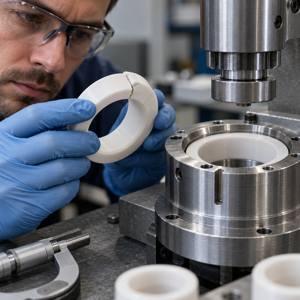
A zirconia sleeve may crack when pressed onto a shaft. A ceramic plate may fracture around a screw hole. A precision ring may split after being installed into a metal housing. Sometimes the component survives assembly but develops delayed cracks after thermal cycling or equipment operation.
Understanding these failures requires looking at the entire mechanical interface rather than only the ceramic material.
For engineers sourcing or designing custom zirconia ceramic parts, the most important factors usually include:
- Fit tolerance
- Interference amount
- Edge geometry
- Hole design
- Contact area
- Clamp force
- Screw preload
- Assembly sequence
- Thermal expansion mismatch
- Defeitos de superfície
1. Zirconia Is Tough for a Ceramic, but It Is Still a Brittle Material
Zirconia is often selected because it offers better fracture toughness than alumina and many other engineering ceramics.
This does not mean that it behaves like metal.
Metals can often redistribute local stress through plastic deformation.
Ceramics generally cannot.
When tensile stress becomes concentrated around a hole, sharp edge, contact point or surface defect, a crack may initiate rapidly.
This is why a zirconia component can have excellent compressive strength and still fail during a seemingly simple assembly process.
The key engineering question is therefore not:
“Is zirconia strong enough?”
It is:
“Where will tensile stress concentrate during assembly?”
2. Excessive Interference Fit Is a Common Cause of Cracking
Press fits are frequently used for bushings, sleeves, rings and insulating components.
For metallic parts, an interference fit may be relatively forgiving.
For zirconia, excessive interference can generate high hoop stress.
Consider a zirconia ring pressed over a metal shaft.
If the shaft diameter is slightly too large, radial pressure develops along the inner diameter of the ceramic.
The ceramic ring may then experience circumferential tensile stress.
Possible results include:
- Immediate splitting during installation
- Radial cracking
- Edge chipping
- Delayed fracture after assembly
- Failure after thermal cycling
The risk becomes higher when:
- The ceramic wall is thin
- The interference value is large
- The part has sharp internal edges
- The shaft has poor roundness
- The ceramic bore is slightly undersized
- Assembly is performed without controlled alignment
Therefore, a nominal diameter alone is not enough.
Engineers should evaluate the full tolerance stack.
3. Tolerance Stack-Up Can Turn a Safe Fit Into a Dangerous Fit
Suppose a design specifies a ceramic bore and metal shaft with nominal dimensions that appear acceptable.
The actual production parts may still produce excessive interference.
Por exemplo:
- Ceramic bore tolerance trends toward minimum size
- Metal shaft tolerance trends toward maximum size
- Surface coating adds additional thickness
- Measurement temperature differs
- Roundness error reduces local clearance
The worst-case combination may be much more severe than the nominal drawing suggests.
For ceramic assemblies, engineers should evaluate:
- Maximum material condition
- Minimum clearance
- Maximum interference
- Roundness
- Cylindricity
- Surface coating thickness
- Measurement uncertainty
A practical design should not depend on the assumption that every component will remain exactly at nominal dimensions.
4. Sharp Internal Corners Create Stress Concentration
One of the most important design rules for zirconia parts is to avoid unnecessarily sharp internal corners.
Stress concentration increases around:
- Internal shoulders
- Square slots
- Blind-hole bottoms
- Rectangular pockets
- Sudden wall-thickness transitions
During assembly, these geometries can become crack initiation points.
Adding a radius can significantly improve stress distribution.
For example, instead of designing a sharp 90-degree transition between two surfaces, consider using a controlled corner radius wherever the mechanical interface allows.
This is especially important in parts such as:
- Zirconia brackets
- Ceramic grippers
- Precision sleeves
- Insulating supports
- Componentes da bomba
- Semiconductor equipment fixtures
5. Edge Chamfers Are Not Only for Easier Assembly
Chamfers are often treated as cosmetic machining details.
For ceramic components, they can have an important mechanical function.
A sharp ceramic edge is vulnerable to localized contact.
During insertion or press fitting, even a small misalignment may cause the mating metal part to push against one edge.
This can create edge chipping or initiate a crack.
A suitable entry chamfer can:
- Improve alignment
- Reduce point loading
- Reduce edge contact
- Lower chipping risk
- Improve assembly repeatability
For sleeves, bushings and rings, both the ceramic component and mating component should be reviewed together.
A chamfer on only one side may not fully eliminate the problem.
6. Screw Holes Are Frequent Crack Initiation Locations
Zirconia plates and structural parts are often mounted using screws.
This introduces several possible failure modes.
Excessive Screw Preload
If the screw is tightened directly against the ceramic surface, high local compressive stress develops under the screw head.
More importantly, bending or tensile stress may develop around the hole.
Over-tightening can therefore cause radial cracks extending away from the mounting hole.
Small Edge Distance
If a screw hole is positioned too close to the edge of the ceramic component, the remaining material may not be sufficient to distribute the load.
Poor Washer Contact
If a washer or clamp does not sit flat against the ceramic surface, the load can become concentrated at one point.
Countersunk Holes
Countersunk geometry can be particularly sensitive because tightening force may introduce radial loading into the ceramic.
For many ceramic assemblies, a through hole with controlled clamping surfaces can be more forgiving than aggressive countersunk fixation.
7. Avoid Point Loading
Ceramics generally perform better when loads are distributed over larger areas.
Problems occur when assembly force is transmitted through a small contact point.
Common examples include:
- Set screws directly contacting ceramic
- Small metal pins pressing against an edge
- Uneven clamp surfaces
- Misaligned washers
- Burrs on metal mating parts
- Localized fixture contact
Even a tiny metal burr can become a high-pressure contact point.
Before assembly, metal interfaces should therefore be inspected for:
- Burrs
- Raised edges
- Tool marks
- Contaminação da superfície
- Particles
- Local deformation
A ceramic part should ideally contact smooth, controlled surfaces.
8. Uneven Clamping Can Create Bending Stress
A flat zirconia plate may appear very strong when loaded uniformly.
However, if it is bolted onto a distorted or non-flat metal frame, tightening the fasteners can force the ceramic to conform to the metal surface.
This creates bending stress.
Possible problems include:
- Corner cracking
- Cracks around mounting holes
- Delayed fracture
- Loss of flatness
- Local contact damage
The ceramic itself may be manufactured within specification, while the actual problem originates from the mating structure.
For precision ceramic mounting, engineers should therefore check:
- Base flatness
- Paralelismo
- Contact pattern
- Screw tightening sequence
- Clamp force distribution
9. Assembly Sequence Matters
Fastener sequence can significantly affect stress distribution.
For a ceramic plate mounted with four or more screws, fully tightening one screw before the others may pull the component unevenly against the support.
A more controlled approach may use:
- Initial light tightening
- Cross-pattern tightening
- Gradual torque increase
- Final controlled torque
The exact procedure depends on the product design.
The important point is that ceramic assembly should not be treated the same way as ordinary metal hardware installation.
10. Screw Torque Should Be Controlled
“Hand-tight” is not a reliable specification.
Different operators may apply very different preload.
For repeatable assembly, especially in production equipment, screw torque should be defined and controlled.
Possible controls include:
- Torque screwdriver
- Torque wrench
- Calibrated electric driver
- Torque-angle procedure
Design engineers may also consider using:
- Load-distributing washers
- Spring washers where appropriate
- Compliant intermediate layers
- Metal inserts
- Shoulder screws
- Controlled spacers
The objective is to prevent uncontrolled mechanical load from being transferred directly into the ceramic.
11. Metal Inserts Can Reduce Direct Ceramic Loading
For some complex zirconia components, metal inserts can improve mounting reliability.
Instead of having screws or shafts directly load the ceramic, an insert can distribute the force.
Possible solutions include:
- Bonded threaded inserts
- Embedded metal sleeves
- Metal mounting frames
- Pressed-in interface components
However, the insert itself must also be designed carefully.
An excessively tight metal insert can simply move the interference problem inside the ceramic.
Bonding area, fit tolerance and thermal expansion must therefore be considered together.
12. Thermal Expansion Mismatch Can Create Delayed Cracks
A zirconia component may survive room-temperature assembly and still crack during operation.
One reason is the difference in coefficient of thermal expansion between the ceramic and surrounding metal.
Consider a zirconia ring mounted tightly around a metal component.
As temperature rises, the metal and zirconia may expand by different amounts.
Depending on the geometry, this can increase interference and mechanical stress.
The effect becomes more important in equipment exposed to:
- Repeated heating and cooling
- High process temperature
- Ciclagem térmica rápida
- Localized heating
Engineers should therefore consider both:
room-temperature fit
e
operating-temperature fit.
13. Avoid Designing Ceramic Assemblies With Zero Tolerance for Movement
Some assemblies unintentionally constrain the ceramic in every direction.
This can be risky.
For example, if a ceramic plate is rigidly fixed at several points while the supporting metal frame expands during operation, the ceramic may be forced to absorb the dimensional change.
A more tolerant mounting design may include:
- Clearance holes
- Floating mounting points
- Slots
- Compliant pads
- Spring-loaded retention
- Controlled gaps
The objective is to locate the ceramic accurately without unnecessarily locking every degree of freedom.
14. Surface Defects Matter During Assembly
Ceramic strength is strongly influenced by surface condition.
Small defects can act as crack initiation sites.
These may include:
- Grinding scratches
- Chips de borda
- Microfissuras
- Machining damage
- Handling damage
A part that passes dimensional inspection may therefore still fail if a critical edge contains a small defect.
High-stress locations should receive particular attention during inspection, especially:
- Hole edges
- Internal corners
- Thin walls
- Contact surfaces
- Press-fit areas
15. Wall Thickness Should Be Reviewed Around Critical Features
Thin-wall zirconia components are possible, but local geometry strongly affects reliability.
Problems often occur where the wall becomes thin around:
- Holes
- Slots
- Grooves
- Esvazamentos
- Threads
- Internal cavities
A common design error is maintaining a reasonable overall wall thickness while leaving very little material around a mounting feature.
Before finalizing the drawing, designers should review the minimum remaining wall rather than only the nominal external thickness.
16. Threading Directly Into Zirconia Requires Caution
Internal threads can sometimes be machined into zirconia.
However, they require careful design.
Threads naturally create many local geometric transitions.
Improper thread geometry or excessive tightening can lead to cracking.
Depending on the application, alternatives may include:
- Through bolts
- Metal threaded inserts
- External clamping
- Bonded interfaces
If ceramic threads are necessary, torque limits should be clearly controlled.
17. Do Not Force Misaligned Parts Together
Assembly misalignment is another common source of damage.
If a zirconia sleeve is installed over a shaft at an angle, contact may occur on only one edge.
Applying greater force does not correct the problem.
It simply increases local stress.
Precision assemblies may benefit from:
- Guide features
- Assembly fixtures
- Controlled insertion tools
- Alignment pins
- Slow axial loading
For press-fit components, assembly force should remain aligned with the designed axis.
18. Monitor Assembly Force
For critical production components, press force can be monitored during assembly.
An abnormal force curve may indicate:
- Excessive interference
- Misalignment
- Contaminação da superfície
- Dimensional error
- Burrs
- Damaged mating parts
This is useful because a ceramic component may appear visually acceptable immediately after installation even if excessive stress has already been introduced.
Force monitoring can therefore become part of production quality control.
19. Inspect Ceramic Parts After Assembly
Post-assembly inspection is often overlooked.
Depending on the importance of the component, inspection may include:
- Visual inspection
- Magnified edge inspection
- Crack inspection
- Dimensional verification
- Runout measurement
- Functional test
This is particularly important when assembly involves:
- Press fitting
- High screw preload
- Thin ceramic sections
- Large temperature changes
- Expensive downstream equipment
20. Typical Zirconia Assembly Failure Modes
Some common failure patterns can provide clues about the root cause.
Radial Crack From a Hole
Possible causes:
- Excessive screw torque
- Hole too close to edge
- Insufficient radius
- Uneven washer contact
Ring Splits Along Its Length
Possible causes:
- Excessive interference
- Shaft oversize
- Ceramic bore undersize
- Expansão térmica
Edge Chipping During Installation
Possible causes:
- Missing chamfer
- Misalignment
- Sharp mating edge
- Impact loading
Crack Appears After Thermal Cycling
Possible causes:
- CTE mismatch
- Residual assembly stress
- Over-constrained mounting
- Existing microcrack
21. Recommended Design Review Before Ordering Zirconia Parts
Before releasing a custom zirconia component for production, engineers should review the assembly interface with the ceramic supplier.
Provide information such as:
- Ceramic drawing
- Mating component drawing
- Diâmetro do eixo
- Housing diameter
- Fit type
- Required clearance
- Screw size
- Tightening torque
- Temperatura de funcionamento
- Thermal cycles
- Applied mechanical load
- Contact surfaces
- Assembly method
This allows the ceramic manufacturer to evaluate whether specific features may create machining or assembly risks.
22. Incoming Inspection Should Include More Than Dimensions
A practical incoming inspection plan for zirconia parts may include:
- Dimensões críticas
- Bore diameter
- Posição do buraco
- Planicidade
- Paralelismo
- Roundness
- Edge condition
- Surface chips
- Acabamento da superfície
- Critical corner geometry
For parts used in press fits or precision positioning, actual dimensional data can be more useful than simple PASS/FAIL results.
23. Prototype Assembly Testing Is Highly Recommended
Before ordering large quantities, assemble a small prototype batch using the actual mating components.
Evaluate:
- Insertion force
- Assembly repeatability
- Fastener torque
- Surface contact
- Edge condition
- Post-assembly cracking
- Thermal cycling behavior
A prototype may reveal interface problems that cannot be identified from ceramic drawings alone.
24. How to Reduce Zirconia Assembly Cracking
A reliable ceramic assembly usually combines several design practices:
- Avoid excessive interference
- Control tolerance stack-up
- Add appropriate chamfers
- Use internal radii
- Avoid point loading
- Increase edge distance around holes
- Control screw torque
- Distribute clamp force
- Improve mating-surface flatness
- Allow thermal movement
- Avoid over-constraining the component
- Inspect critical ceramic edges
- Validate the design using prototype assembly
No single rule solves every problem.
The assembly must be evaluated as a complete mechanical system.
Conclusão
When zirconia ceramic parts crack during assembly, the root cause is often not simply “ceramic brittleness.”
Many failures originate from the mechanical interface:
too much interference, sharp edges, concentrated contact, excessive screw preload, poor alignment or thermal expansion mismatch.
Because ceramics cannot redistribute stress like ductile metals, small design details can have a major effect on reliability.
For custom zirconia parts, the best approach is to review the ceramic geometry and mating structure together before production.
A successful design should consider:
Fit → Edge geometry → Contact area → Mounting force → Thermal movement
By controlling these factors early in the design stage, equipment manufacturers can significantly reduce assembly cracking, field failures and unnecessary replacement costs.
FAQ
Why does a zirconia sleeve crack during press fitting?
The most common causes are excessive interference, shaft oversize, ceramic bore undersize, poor alignment and localized edge loading. The complete tolerance stack should be checked before increasing assembly force.
Can screws be used to mount zirconia ceramic parts?
Yes, but screw torque, hole geometry, edge distance and load distribution must be controlled. Direct high preload against ceramic surfaces can cause cracking around mounting holes.
Should zirconia parts be mounted tightly to prevent movement?
Not always. Excessively rigid mounting can generate stress during assembly or thermal expansion. Some applications benefit from controlled clearance, compliant interfaces or floating mounting points.