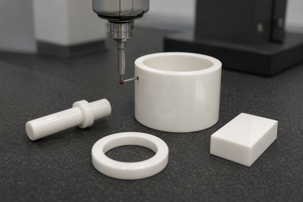
Zirconia ceramic parts are widely used in applications requiring high strength, fracture toughness, wear resistance, electrical insulation and a smooth working surface. Typical products include ceramic shafts, sleeves, bushings, plungers, valve components, positioning pins, guides, nozzles and semiconductor equipment parts.
However, specifying a zirconia component cannot be handled in exactly the same way as specifying a metal part. Zirconia is formed, sintered and often diamond-ground after firing. Sintering shrinkage, part geometry, grinding access, wall thickness and inspection methods all affect the tolerances that can be achieved.
A good zirconia drawing should identify the dimensions that are functionally critical, the surfaces that require grinding or polishing, the required geometric tolerances and the inspection method used for acceptance.
Why Zirconia Tolerances Require Special Planning
Zirconia is one of the strongest and toughest structural ceramics at room temperature. Its wear resistance and ability to achieve a smooth surface make it suitable for sliding, pumping and precision mechanical applications. Kyocera’s zirconia material overview
These properties also make finished zirconia difficult to machine with conventional cutting tools. Precision dimensions are normally produced through diamond grinding, lapping or polishing after sintering.
The general manufacturing sequence may include:
- パウダーの準備
- Forming or molding
- グリーン加工
- 焼結
- ダイヤモンド研削
- Lapping or polishing
- クリーニング
- Dimensional and visual inspection
Dimensional variation can occur during forming and sintering. Post-sinter grinding is therefore required when a part needs close fits, controlled flatness, accurate holes or fine surface finishes.
Grinding is an established finishing method for achieving precision tolerances in technical ceramic components. CoorsTek ceramic finishing methods
Key Tolerance Items for Zirconia Parts
| Drawing requirement | その重要性 |
|---|---|
| Linear dimensions | Controls overall fit and installation |
| Outside diameter | Important for shafts, plungers and positioning features |
| Inside diameter | Controls sleeve, bearing and valve clearance |
| 厚さ | Affects mechanical strength and assembly height |
| 平坦性 | Important for sealing and mounting surfaces |
| 並列処理 | Controls uniform gaps and assembled alignment |
| 垂直度 | Maintains accurate shoulders and end faces |
| Cylindricity | Controls motion and sealing performance |
| Circular runout | Important for rotating parts |
| True position | Controls hole and feature locations |
| 表面粗さ | Affects friction, wear, sealing and particle generation |
| 境界条件 | Reduces chipping and handling damage |
1. As-Sintered Versus Precision-Ground Dimensions
The first decision is whether a feature can remain as-sintered or must be ground after firing.
As-sintered features
As-sintered dimensions are produced by the forming and sintering process without final precision grinding.
They are generally suitable for:
- Non-mating external surfaces
- Clearance features
- 保護カバー
- Areas with generous assembly gaps
- High-volume molded geometries
- Surfaces that do not control motion or sealing
As-sintered tolerances are influenced by:
- Part length and thickness
- Wall-thickness uniformity
- Forming direction
- Powder distribution
- Tool wear
- Sintering shrinkage
- Furnace loading
- Material grade
- Batch-to-batch variation
Because these factors vary by geometry and process, as-sintered tolerances are usually defined according to the supplier’s manufacturing capability rather than a universal tolerance value.
Precision-ground features
Diamond grinding is used when dimensions directly affect assembly or equipment performance.
Typical ground features include:
- Shaft outside diameters
- Sleeve inside diameters
- Reference faces
- シール面
- Positioning shoulders
- Precision thickness
- Mounting interfaces
- バルブシート
- Guide surfaces
Grinding improves dimensional control but increases cost, manufacturing time and inspection requirements. It is therefore better to grind only the functionally important surfaces.
2. Practical Dimensional Tolerance Levels
There is no single tolerance that applies to every zirconia ceramic part. Capability depends on material grade, dimension, shape, grinding access, wall thickness and order quantity.
The following table can be used as an RFQ discussion framework rather than a universal manufacturing guarantee.
| Tolerance level | Indicative requirement | Typical application |
| General ceramic tolerance | Supplier standard or percentage-based | Non-mating as-sintered features |
| Standard precision | Approximately ±0.02 to ±0.05 mm | Mounting and general assembly features |
| Tight precision | Approximately ±0.01 to ±0.02 mm | Shafts, sleeves, guides and positioning parts |
| Critical precision | Approximately ±0.005 to ±0.01 mm | Precision fits and controlled clearances |
| Ultra-precision | Drawing review required | Metrology, semiconductor and high-accuracy motion systems |
These ranges are starting points for technical discussion. Achievable tolerances should be confirmed against the actual drawing.
A ±0.01 mm tolerance on a simple outside diameter may be reasonable, while the same tolerance on a deep internal bore, thin wall or long curved component may require a different manufacturing approach.
3. Tolerance Depends on Feature Size
A tolerance should always be evaluated relative to the nominal dimension.
例えば、こうだ:
- A ±0.01 mm tolerance on a 5 mm diameter pin may be achievable by centerless or cylindrical grinding.
- The same tolerance on a 300 mm ceramic plate may require specialized grinding and detailed flatness control.
- A small through-hole may be easier to inspect than a long, deep blind bore.
- A short sleeve may maintain cylindricity more easily than a long, thin-wall tube.
The RFQ should therefore include:
- Nominal dimension
- 寛容
- Feature length
- Wall thickness
- 深さ対直径比
- Required surface finish
- Related geometric tolerance
- 検査方法
4. Controlling Outside and Inside Diameters
Zirconia shafts, pins, plungers and bushings often require controlled diameters.
Outside diameters
Important specifications may include:
- Diameter tolerance
- Cylindricity
- 真直度
- Circular runout
- 表面粗さ
- End-face perpendicularity
- Chamfer or edge radius
A diameter tolerance alone does not ensure that a long shaft is straight or cylindrical.
For rotating parts, circular or total runout relative to a functional datum may provide a better control than diameter alone.
Inside diameters
Internal zirconia bores are generally more difficult to grind and inspect than external diameters.
Cost and feasibility are affected by:
- Bore diameter
- Bore depth
- Through-hole or blind-hole design
- Wall thickness
- Required cylindricity
- 表面仕上げ
- Internal shoulder geometry
- 研削工具へのアクセス
Deep, narrow bores and sharp internal corners should be avoided when possible. A through-hole with a practical diameter is generally easier to grind and inspect than a deep blind bore.
5. Flatness, Parallelism and Perpendicularity
Geometric tolerances are critical for zirconia plates, valve components, spacers, guides and sealing parts.
平坦性
Flatness controls the variation of a surface without referencing another surface.
It is important for:
- Vacuum sealing surfaces
- Ceramic valve seats
- Mounting plates
- 半導体治具
- ウェアプレート
- Lapped interfaces
Flatness capability depends heavily on the surface area, thickness and support conditions during measurement.
並列処理
Parallelism controls the orientation between two surfaces.
It is commonly specified for:
- Precision spacers
- Washers
- バルブ部品
- Sliding plates
- セラミック基板
- Mounting blocks
A thickness tolerance does not automatically control parallelism. Both requirements may be necessary.
垂直度
Perpendicularity is important for shoulders, end faces, mounting surfaces and shaft features.
For example, a zirconia shaft may meet its diameter tolerance but still cause assembly misalignment if its end face is not perpendicular to its central axis.
6. Surface Finish Requirements
Surface finish influences friction, wear, sealing, cleaning and particle generation.
Common surface conditions include:
| 表面の状態 | Indicative roughness level | Typical use |
| As-sintered | Supplier standard | Non-contact surfaces |
| Standard ground | Ra 0.4–0.8 μm | General mechanical components |
| Fine ground | Ra 0.2–0.4 μm | Sliding and positioning parts |
| Lapped | Ra 0.1–0.2 μm | Sealing and precision contact surfaces |
| Polished | Ra 0.05–0.1 μm or better | Low-friction and high-cleanliness applications |
These values are general RFQ reference levels. Actual surface finish depends on material grade, part geometry, polishing direction and inspection method.
Do not specify roughness without identifying the surface
A drawing should clearly identify which surfaces require:
- As-sintered condition
- 研磨
- Fine grinding
- ラッピング
- 研磨
- Mirror finishing
Applying a polished finish to every surface usually increases cost without improving performance.
Ra is not the only parameter
Ra is the most commonly used roughness parameter, but some applications may also need:
- Rz
- Maximum profile height
- Waviness
- Lay direction
- Surface defect limits
- Pore or pull-out limits
- Scratch requirements
For sealing and sliding surfaces, the measurement direction and cutoff settings should be agreed upon in advance.
7. Edge Chamfers and Corner Radii
Sharp ceramic edges are more vulnerable to chipping during grinding, cleaning, packaging and assembly.
The drawing should specify:
- Chamfer width
- Chamfer angle
- エッジ半径
- Maximum edge break
- Burr and chip requirements
- Critical contact edges
Small chamfers or radii can improve handling strength and reduce accidental edge damage.
Sharp internal corners should also be avoided. A practical internal radius improves forming, sintering and grinding reliability.
The radius should be designed according to the available grinding wheel or forming tool.
8. Using GD&T on Zirconia Drawings
Geometric dimensioning and tolerancing can make zirconia drawings easier to manufacture and inspect.
A clear datum system should reflect how the part functions in the final assembly.
例えば、こうだ:
- Datum A: Primary mounting surface
- Datum B: Precision outside diameter
- Datum C: Positioning flat or hole
Features can then be controlled using:
- 役職
- 平坦性
- 並列処理
- 垂直度
- Cylindricity
- Profile
- Circular runout
- Total runout
Avoid applying very tight profile or position tolerances to the entire ceramic component unless functionally necessary.
It is usually more economical to identify a small number of precision datum and mating features while allowing non-critical surfaces to follow general ceramic tolerances.
9. Inspection Methods for Zirconia Parts
Inspection equipment should be selected according to feature size, tolerance and surface condition.
| Inspection requirement | Possible method |
| Outside diameter | Micrometer, laser measurement or CMM |
| Inside diameter | Bore gauge, air gauge, pin gauge or CMM |
| Length and thickness | Micrometer, height gauge or CMM |
| 平坦性 | CMM, optical flat or interferometric method |
| 並列処理 | CMM or precision height measurement |
| 垂直度 | CMM or precision fixture |
| Roundness | Roundness measuring instrument |
| 振れ | Rotary fixture with displacement indicator |
| Hole position | CMM or vision measuring system |
| 表面粗さ | Contact or optical profilometer |
| エッジチップ | Controlled visual or microscope inspection |
| Internal defects | Ultrasonic, X-ray or other project-specific NDT |
Measurement force matters
Thin or small ceramic parts can be affected by excessive contact force during inspection. Measurement pressure, fixture support and probe size should be appropriate for the component.
Define the measurement temperature
Precision dimensions should normally be inspected under controlled temperature conditions. The drawing or inspection agreement should state the reference temperature when dimensional accuracy is critical.
10. Visual Inspection Requirements
Dimensional conformity does not automatically mean that a zirconia part is visually acceptable.
Visual inspection may cover:
- Cracks
- Chips
- Edge damage
- Surface pits
- Grinding marks
- Discoloration
- Contamination
- Polishing defects
- Material inclusions
- Incomplete features
The acceptance criteria should define:
- Maximum allowed chip size
- Critical and non-critical surfaces
- Inspection lighting
- Inspection magnification
- Viewing distance
- Sample or 100% inspection
- Approved reference samples when necessary
Terms such as “no chips” or “perfect surface” can be difficult to apply consistently without measurable criteria.
11. Inspection Reports and Traceability
For precision zirconia components, customers may request:
- First Article Inspection Report
- 寸法検査報告書
- 材料証明書
- 表面粗さ報告書
- Flatness or roundness report
- Visual inspection record
- Lot number
- Manufacturing date
- Cleaning record
- Packaging record
- Certificate of Conformance
The RFQ should specify whether the report is required for:
- The first prototype
- Every production lot
- Selected samples
- Every individual part
Requiring a complete report for every part can significantly increase cost, so the reporting level should match the application risk.
12. Design Features That Increase Manufacturing Cost
The following requirements usually increase the cost of zirconia ceramic parts:
- Tight tolerances on every dimension
- Deep narrow bores
- Very thin walls
- Large flat surfaces
- Sharp internal corners
- Small internal threads
- Multiple precision datums
- Interrupted grinding surfaces
- Tight flatness on thin parts
- Ultra-low roughness over large areas
- Complex profiles requiring extensive hard grinding
- 100% inspection of all dimensions
A design review before quotation can often identify lower-cost alternatives without affecting function.
13. Zirconia Ceramic Parts RFQ Checklist
Provide the following information when requesting a quotation:
- 2D drawing and 3D model
- Zirconia grade or application environment
- 全体寸法
- Critical linear tolerances
- Required GD&T controls
- データ構造
- As-sintered and ground surfaces
- Surface roughness requirements
- Chamfers and edge radii
- Acceptable chip and visual limits
- 動作温度
- Mechanical load
- 化学物質への暴露
- Wear or sliding conditions
- Electrical insulation or ESD requirement
- 清掃に関する要件
- 検査方法
- 検査報告書の要件
- 試作数量
- Estimated annual quantity
If the zirconia grade has not been selected, provide the application conditions so the supplier can evaluate material options.
Common Specification Mistakes
Using metal tolerances on every ceramic feature
Zirconia can be precision-ground, but applying metal-machining tolerances to the complete part can create unnecessary cost.
Specifying only dimensional tolerances
Critical ceramic components may also need flatness, parallelism, runout and surface-finish controls.
Ignoring inspection accessibility
A tolerance is not useful if the feature cannot be measured reliably.
Requesting a polished finish everywhere
Only functional sliding, sealing or cleanliness-critical surfaces normally require polishing.
Using sharp corners
Sharp edges increase chipping risk and may require special processing.
Failing to identify critical dimensions
The manufacturer needs to know which features control assembly, sealing, movement or alignment.
よくある質問
What tolerance can be achieved on zirconia ceramic parts?
Achievable tolerance depends on feature size, geometry, material grade and grinding access. Standard precision-ground dimensions may fall around ±0.02 to ±0.05 mm, while tighter features may reach ±0.005 to ±0.02 mm after detailed drawing review.
Can zirconia parts be polished to a mirror finish?
Yes. Zirconia can achieve a very smooth polished surface, making it suitable for sliding, sealing and wear applications. The achievable finish depends on material microstructure and geometry.
Is an as-sintered zirconia surface suitable for a precision fit?
Usually not. Precision fits generally require post-sinter diamond grinding because sintering variation affects final dimensions.
Should flatness and thickness tolerance both be specified?
Yes, when both surface form and overall thickness affect the assembly. Thickness tolerance alone does not control flatness or parallelism.
Can deep holes be precision-ground in zirconia?
They may be possible, but feasibility depends on diameter, depth, wall thickness, required finish and tool access. Deep blind holes are generally more difficult than through-holes.
How should zirconia parts be inspected?
Inspection may include CMM measurement, micrometers, bore gauges, roundness instruments, profilometers, optical systems and visual inspection. The selected method should match the tolerance and feature geometry.
Does tighter tolerance always improve performance?
No. Tolerances should be based on assembly and functional requirements. Unnecessarily tight tolerances increase cost, inspection time and manufacturing risk.
What documents should be included with an RFQ?
Provide a dimensioned drawing, 3D model, material requirement, critical tolerances, surface finish, inspection criteria, application conditions and quantity.
結論
Successful zirconia ceramic components begin with a drawing that clearly separates critical precision features from general ceramic surfaces.
Dimensional tolerances, flatness, parallelism, runout, surface roughness and edge requirements should be selected according to actual assembly and operating needs. Inspection methods should also be agreed upon before production to prevent differences in measurement results.
XKH Ceramics can review zirconia component drawings, tolerance requirements, surface finishes and inspection documents for prototype and production projects. Providing complete application and drawing information helps improve manufacturability, quotation accuracy and delivery reliability.