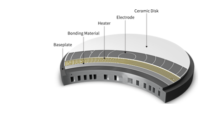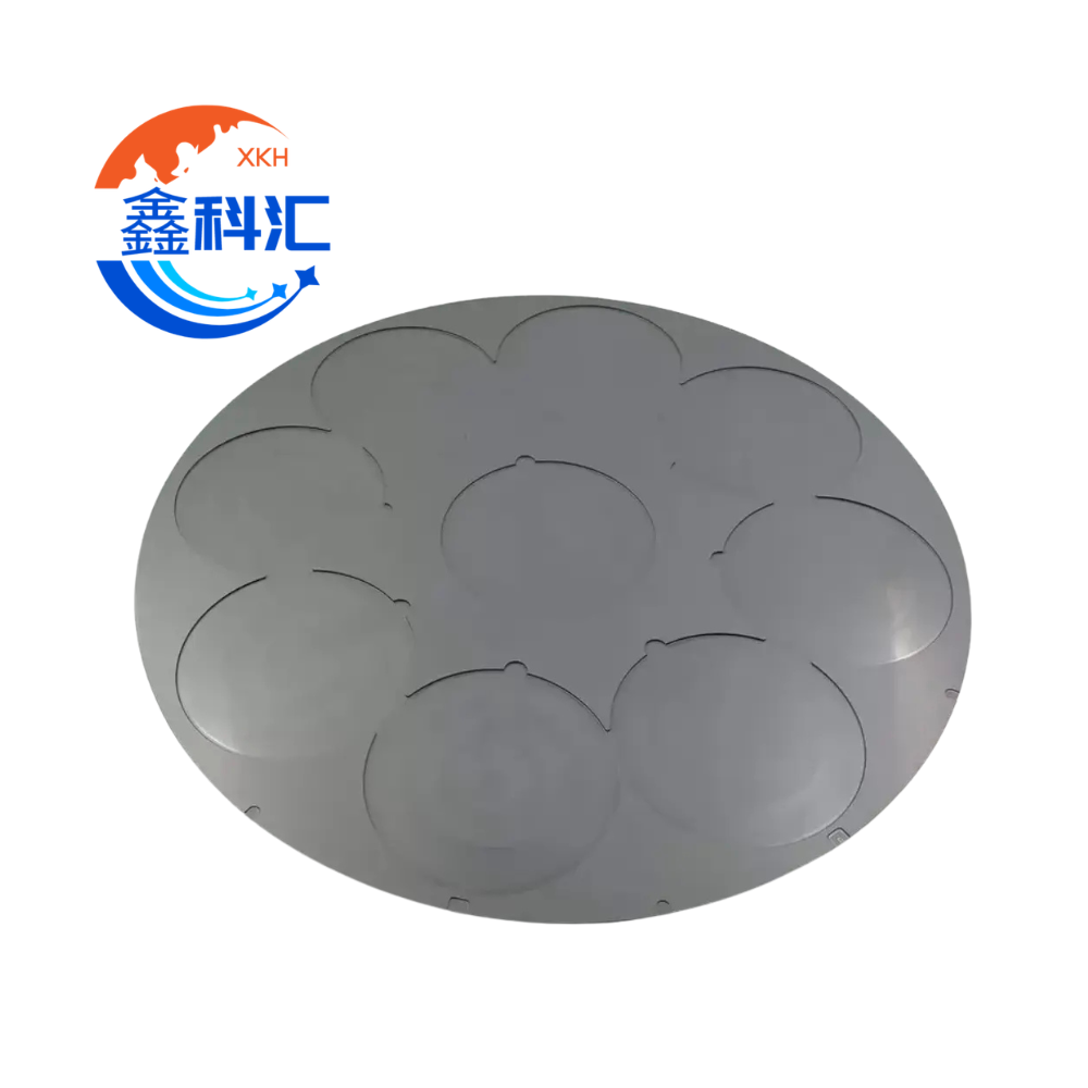
The rapid growth of AI clusters is changing not only processors and networking architectures, but also the materials used inside advanced packages.
As electrical links become more difficult to scale at extremely high bandwidths, optical interconnects are moving closer to switch ASICs, accelerators and other high-performance silicon.
This transition is driving the development of Co-Packaged Optics (CPO) and increasingly compact optical engines.
However, moving photonic devices closer to high-power electronics creates a new problem:
heat.
Optical engines contain temperature-sensitive components such as lasers, photonic integrated circuits, drivers, transimpedance amplifiers and optical coupling structures.
At the same time, nearby ASICs can generate substantial heat.
Thermal management therefore becomes a package-level materials problem rather than simply a heatsink problem.
Tässä kohtaa aluminum nitride (AlN) ceramic heat spreaders, submounts and metallized ceramic substrates become increasingly relevant.
AlN combines:
- high thermal conductivity;
- electrical insulation;
- relatively low coefficient of thermal expansion;
- compatibility with semiconductor packaging;
- precision machining capability;
- thin-film and thick-film metallization options;
- mechanical stability.
But choosing AlN only because it has “high thermal conductivity” is not enough.
For AI optical engines and CPO packaging, engineers must consider thermal conductivity, CTE, metallization, flatness, thickness tolerance, surface finish, bonding and long-term thermal cycling together.
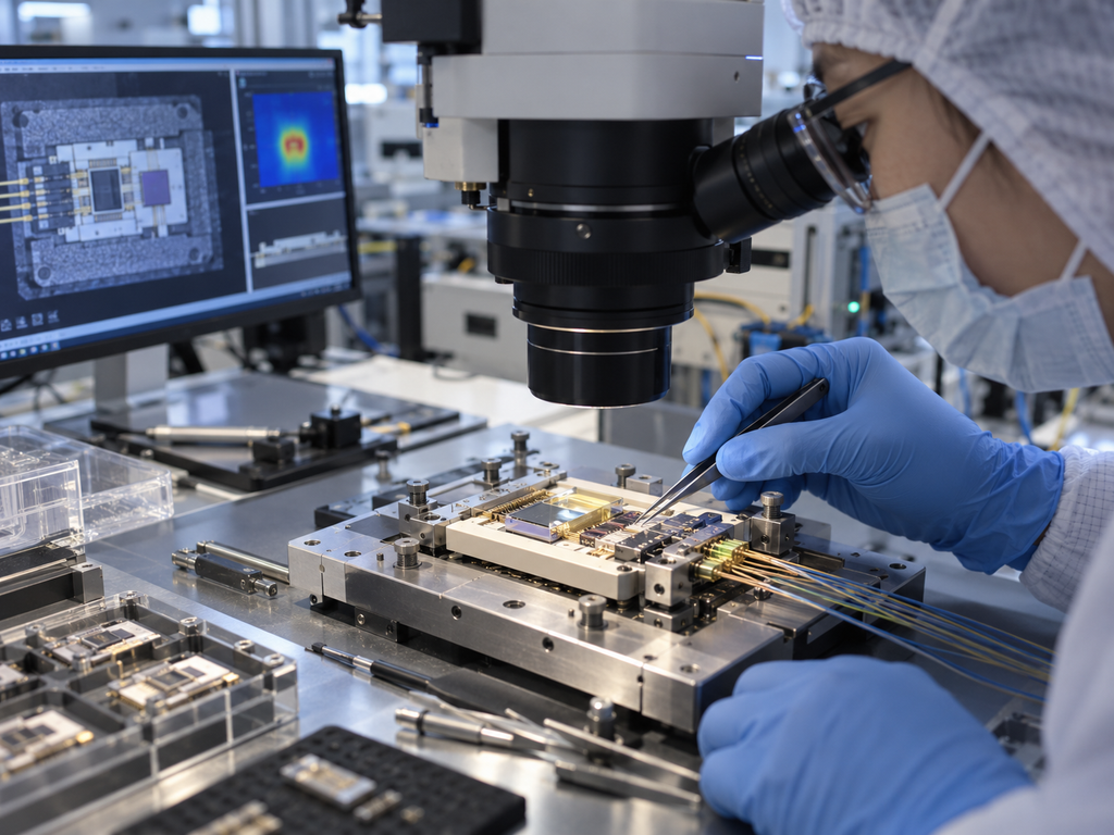
Why CPO Creates a New Thermal Management Challenge
Traditional pluggable optical modules are physically separated from the highest-power switch silicon.
CPO changes this architecture.
Optical engines are placed much closer to the switch ASIC or other processing devices in order to shorten high-speed electrical connections.
This can improve bandwidth density and energy efficiency, but it also creates stronger thermal interaction between electronic and photonic components.
The problem is especially important because optical devices can be highly temperature sensitive.
Temperature variation may influence:
- laser wavelength;
- optical output power;
- microring resonance;
- modulator behavior;
- photodetector performance;
- fiber alignment;
- coupling efficiency;
- electronic driver performance.
Therefore, the objective is not simply to reduce maximum temperature.
The package must also control:
temperature uniformity, thermal gradients and thermo-mechanical movement.
A material capable of spreading heat rapidly while maintaining dimensional stability becomes valuable in this environment.
What Is an AlN Ceramic Heat Spreader?
A heat spreader distributes heat laterally before the heat reaches another thermal-management layer such as a cold plate, heatsink or package lid.
For an optical engine, an AlN component may serve as:
- laser diode submount;
- PIC submount;
- EIC submount;
- ceramic carrier;
- thermal spreader;
- electrically insulating heat-transfer plate;
- metallized substrate;
- package base;
- interface between semiconductor devices and metal cooling structures.
The exact configuration depends on the optical architecture.
Some designs require a simple polished AlN plate.
Others require complex machining, patterned metallization, AuSn die-attach layers, vias, conductor traces or brazed metal components.
Therefore, “AlN heat spreader” can describe several different component types.
1. Thermal Conductivity: The Main Advantage of AlN
The primary reason for using aluminum nitride is its combination of high thermal conductivity and electrical insulation.
Commercial semiconductor-grade AlN commonly offers thermal conductivity well above that of conventional alumina.
Depending on composition and manufacturing process, published commercial AlN grades can range from approximately 150 W/m·K to above 200 W/m·K.
For example, commercially available AlN ceramic substrates include grades around 150–170 W/m·K as well as higher-conductivity grades approaching approximately 240 W/m·K.
This makes AlN attractive when heat must be removed from a concentrated source without electrically connecting the device to the cooling structure.
Why Heat Spreading Matters in Optical Engines
Consider a laser or electrical driver mounted on a relatively small die area.
If the thermal conductivity of the underlying material is low, heat remains concentrated beneath the device.
This creates a local hotspot.
A high-thermal-conductivity AlN plate spreads that heat laterally before it enters the next package layer.
The effective thermal path may look like:
Laser / PIC / EIC
↓
Die Attach
↓
AlN Ceramic Submount
↓
TIM / Solder / Bond Layer
↓
Heat Spreader or Cold Plate
↓
System Cooling
Every interface adds thermal resistance.
Therefore, specifying a very high-conductivity AlN material does not automatically guarantee a low device temperature.
The complete thermal path must be optimized.
2. Do Not Specify Thermal Conductivity Alone
A common RFQ might simply state:
Material: AlN
Thermal Conductivity: ≥170 W/m·K
This is useful, but incomplete.
The thermal performance of the final assembly also depends on:
- AlN thickness;
- contact area;
- ceramic flatness;
- metallization thickness;
- solder or TIM thickness;
- interface voids;
- surface roughness;
- heat-source position;
- cooling plate geometry.
For example, a high-conductivity ceramic with a poorly controlled bonding interface can still produce high thermal resistance.
Similarly, excessive thickness increases the vertical heat-transfer distance.
Therefore, heat spreader thickness should be optimized according to both mechanical and thermal requirements.
3. CTE Matching Is Critical for CPO Reliability
Thermal conductivity receives most of the attention, but coefficient of thermal expansion, or CTE, is equally important.
When a package heats from assembly temperature to operating temperature, each material expands.
Silicon, ceramic, copper, solder, glass, polymers and optical fibers all expand at different rates.
If two bonded materials have significantly different CTE values, thermal cycling creates mechanical stress at the interface.
Over time this can contribute to:
- solder fatigue;
- die-attach cracking;
- ceramic cracking;
- delamination;
- warpage;
- optical misalignment;
- changes in coupling efficiency.
This is particularly important for CPO because optical alignment tolerances can be much tighter than ordinary electrical interconnection tolerances.
Why AlN Works Well with Silicon
AlN has a relatively low CTE compared with many conventional packaging materials.
Typical commercial values are approximately 4.5–5.5 ppm/K, depending on temperature range and material grade.
Silicon also has a relatively low CTE.
This makes AlN a useful intermediate material between semiconductor dies and higher-CTE metals.
Commercial AlN packaging materials are specifically promoted for their CTE compatibility with silicon because reduced mismatch can lower thermomechanical stress.
For an optical-engine designer, that means the ceramic should not be selected based solely on thermal conductivity.
The full material stack should be evaluated.
4. CTE Becomes More Important as the Package Gets Larger
A small CTE mismatch across a tiny component may create limited displacement.
Across a large CPO package, however, the same mismatch can create considerably greater dimensional change.
This becomes especially important for structures containing:
- large silicon dies;
- silicon photonics PICs;
- glass interposers;
- fiber array units;
- laser assemblies;
- ceramic submounts;
- copper heat spreaders.
As package dimensions increase, thermally induced displacement can affect both mechanical reliability and optical positioning.
That means an AlN heat spreader may need to perform two functions simultaneously:
transfer heat efficiently while mechanically stabilizing the optical package.
5. Flatness Is a Functional Specification
For high-end optical packaging, AlN flatness should not be treated simply as a cosmetic drawing requirement.
Flatness directly affects assembly.
Poor flatness may create non-uniform contact between:
- ceramic and die;
- ceramic and TIM;
- ceramic and heatsink;
- ceramic and optical-engine base.
This can generate local air gaps or uneven bonding thickness.
The result can be increased thermal resistance and localized stress.
In optical assemblies, deformation can also influence component height and alignment.
Important Geometry Specifications
Depending on component size and application, an RFQ may include:
- overall flatness;
- local flatness;
- parallelism;
- thickness;
- thickness tolerance;
- total thickness variation;
- surface roughness;
- edge profile;
- chamfer dimensions;
- hole position;
- metallization alignment.
These parameters should be connected to the actual assembly process.
Simply demanding the tightest achievable tolerance may unnecessarily increase cost.
6. Large AlN Plates Require More Careful Flatness Control
As AlN components become larger, maintaining tight flatness becomes more difficult.
Manufacturing steps such as:
- ceramic sintering;
- grinding;
- lapping;
- polishing;
- metallization;
- brazing;
- thermal processing
can each influence the final geometry.
A plate that is flat after ceramic machining may change slightly after metallization or metal attachment.
Therefore, the drawing should clarify whether the flatness requirement applies:
before metallization, after metallization, or after final assembly.
For high-precision optical engines, the final assembled geometry is often the most important condition.
7. Metallization Turns the Ceramic into a Packaging Platform
Many AlN components used in optical engines are not simply bare ceramic plates.
They require metallized surfaces for die attach, wire bonding, soldering, grounding or hermetic packaging.
Common metallization approaches can include:
- thin-film metallization;
- thick-film metallization;
- tungsten-based co-fired conductors;
- Mo/Mn systems;
- Ti/Pt/Au;
- TiW/Au;
- Ni/Au;
- Cu-based structures;
- direct bonded copper;
- active-metal brazing systems.
The correct structure depends on the application.
Laser and Optical Submount Metallization
Laser submounts frequently require very precise metal patterns.
Possible requirements include:
- AuSn solder areas;
- Au wire-bonding pads;
- ground connections;
- electrical isolation regions;
- alignment marks;
- thermal paths.
High-power laser packages may use an AlN submount specifically because it can simultaneously provide thermal conduction and electrical insulation.
Commercial semiconductor ceramic manufacturers already offer AlN laser-diode submounts with thin-film structures and AuSn deposition.
8. Metallization Adds New Reliability Challenges
Adding metal to ceramic creates another CTE interface.
The ceramic and metal do not expand identically.
During repeated thermal cycling, stress can concentrate near:
- metal edges;
- corners;
- vias;
- solder joints;
- brazed interfaces.
Possible failure mechanisms include:
- metal delamination;
- ceramic cracking;
- solder fatigue;
- interface void growth;
- increased thermal resistance.
Therefore, metallization should be designed according to both electrical requirements and mechanical reliability.
A thicker metal layer is not automatically better.
Likewise, maximizing metal coverage may create unnecessary stress.
Finite-element thermal-mechanical simulation can be useful for larger or higher-power packages.
9. Surface Finish Affects Both Thermal and Assembly Performance
AlN surfaces can be supplied as:
- as-fired;
- ground;
- lapped;
- polished.
The correct surface condition depends on the assembly.
A polished surface may be required for:
- thin-film metallization;
- precise die attach;
- optical alignment structures;
- very thin bond lines.
A ground finish may be sufficient for other heat-spreading applications.
Surface roughness also affects interface behavior.
Too much roughness can increase the effective bond-line thickness or create voids.
However, a surface should not be specified as extremely smooth without understanding the bonding process.
Some adhesives or metallization processes require a certain surface condition for adhesion.
10. Thermal Interface Quality Can Matter More Than Ceramic Conductivity
Consider two AlN materials:
Material A has slightly higher thermal conductivity.
Material B has slightly lower thermal conductivity but achieves:
- better flatness;
- thinner bond line;
- fewer interface voids;
- more uniform metallization.
In a real package, Material B may provide better total thermal performance.
This is why thermal design must evaluate thermal resistance of the complete stack, not simply the bulk conductivity of the ceramic.
For high-power optical engines, important interface controls include:
- TIM thickness;
- solder thickness;
- void percentage;
- wetting;
- bond-line uniformity;
- interface roughness;
- assembly pressure.
11. Optical Engines Introduce a Unique Temperature-Stability Requirement
A processor mainly needs to remain within an acceptable operating temperature range.
Optical devices may require something more demanding:
stable temperature.
A small temperature change can shift the optical wavelength of a laser or resonance wavelength of a silicon photonic device.
Therefore, the most important thermal metric may sometimes be:
- temperature gradient;
- transient temperature response;
- optical-engine-to-ASIC thermal coupling;
rather than simply peak temperature.
Recent CPO thermal-management research increasingly emphasizes thermal crosstalk between ASICs and optical engines.
This means heat spreading must be carefully controlled.
Moving heat away from one device is beneficial, but spreading that heat into a temperature-sensitive optical component may not be.
Thus the package may require both:
high-conductivity thermal paths and thermal isolation zones.
12. Thermal Spreading and Thermal Isolation Must Be Designed Together
This is an important distinction for CPO systems.
AlN is an excellent heat-spreading material.
But designers do not necessarily want heat to spread everywhere.
Esimerkiksi:
A high-power driver may need rapid heat transfer into the cooling plate.
A nearby laser may need to remain thermally isolated from that driver.
Therefore, the optimal ceramic design could include:
- separate AlN submounts;
- patterned metal regions;
- controlled ceramic thickness;
- localized thermal vias;
- low-conductivity isolation regions;
- dedicated cooling paths.
This becomes a package architecture question rather than simply a ceramic-material question.
13. Warpage Can Affect Optical Coupling
Warpage is particularly dangerous in optical packaging.
Electrical solder connections may tolerate a certain amount of dimensional movement.
Optical coupling efficiency can be much more sensitive to alignment.
Thermal deformation may affect the relationship between:
- PIC and fiber array;
- laser and waveguide;
- lens and photonic die;
- optical connector and package;
- submount and interposer.
Recent CPO thermal research specifically identifies thermal expansion mismatch and warpage as potential sources of fiber-array misalignment and optical coupling degradation.
Therefore, ceramic flatness and CTE must be considered together.
14. Reliability Testing for AlN Optical Packaging
An AlN heat spreader should not be qualified only by dimensional inspection.
Depending on the package architecture, reliability evaluation may include:
Thermal Cycling
Used to evaluate repeated expansion and contraction of ceramic, metal and bonding layers.
High-Temperature Storage
Used to evaluate material and interface stability during long-term temperature exposure.
Temperature and Humidity Testing
Important for assemblies containing metals, polymers, adhesives or exposed interfaces.
Mechanical Testing
May include bending, shear, pull testing or die-attach strength.
Metallization Adhesion
Verifies that metal layers remain attached to the ceramic substrate.
Thermal Resistance Measurement
Used to determine whether thermal performance changes after reliability testing.
Optical Performance Testing
For a completed CPO module, optical output, wavelength and coupling loss may also need to be monitored before and after thermal cycling.
15. AlN vs Alumina for AI Optical Packaging
Alumina remains one of the most widely used electronic ceramics.
It offers:
- good electrical insulation;
- good mechanical strength;
- mature manufacturing processes;
- lower cost.
However, AlN typically offers much higher thermal conductivity and a CTE closer to silicon.
Therefore, AlN becomes especially attractive when thermal density increases.
| Requirement | AlN | Alumiinioksidi |
|---|---|---|
| High heat spreading | Erinomainen | Kohtalainen |
| Sähköinen eristys | Erinomainen | Erinomainen |
| CTE matching with Si | Very good | Kohtalainen |
| Semiconductor packaging maturity | Korkea | Erittäin korkea |
| Fine metallization | Saatavilla | Saatavilla |
| Kustannukset | Korkeampi | Alempi |
| High-power laser / optical engine | Strong candidate | Application-dependent |
This does not mean every optical component should use AlN.
The correct decision depends on heat load, package size, mechanical requirements and cost.
16. What Should Be Specified in an AlN Heat Spreader RFQ?
For custom AI optical-engine and CPO applications, a useful RFQ should include more than overall dimensions.
Recommended information includes:
Hakemus
CPO / optical engine / silicon photonics / laser / EIC / PIC
Materiaali
Aluminum Nitride, including required grade where known
Lämmönjohtavuus
Minimum required value if critical
Dimensions
Length × width × thickness
Thickness Tolerance
Especially important for optical stack height
Flatness
Specify measurement condition and reference surface
Parallelism
Where assembly height is critical
Pinnan karheus
For bonding or thin-film processing
Metallization
Material stack and pattern
Metal Thickness
Including tolerance
Solder Layer
AuSn or other die-attach requirement if applicable
Hole / Slot Geometry
Where mechanical or optical alignment is required
Käyttölämpötila
Thermal Cycling Requirement
Bonding Method
Assembly Drawing
Määrä
Prototype and expected production volume
A STEP file and 2D drawing are especially useful for components with complex machining or metallization.
17. Questions to Ask Before Manufacturing
Before quoting a custom AlN optical-engine component, several engineering questions should be clarified.
Is the component primarily a heat spreader or an electrical substrate?
This determines whether metallization and insulation structures are required.
What device will be mounted on the ceramic?
Laser, PIC, EIC, driver and ASIC packages may have different thermal requirements.
Where does the heat ultimately go?
The cooling path must be understood.
What is the maximum allowable warpage?
This may be more important than bulk material properties.
Is thin-film metallization required?
If yes, polished surface quality may be necessary.
Will the ceramic be soldered or brazed to metal?
CTE mismatch and thermal cycling must then be considered.
Is optical alignment dependent on ceramic thickness?
If yes, thickness tolerance and parallelism become critical.
18. Prototype Qualification Before Volume Production
For a new CPO or optical-engine project, prototype ceramic components should ideally be qualified before high-volume production.
A typical sequence can include:
Step 1 — Material confirmation
Confirm AlN grade and thermal properties.
Step 2 — Dimensional inspection
Check thickness, flatness, parallelism and critical features.
Step 3 — Metallization inspection
Check pattern dimensions, thickness and adhesion.
Step 4 — Assembly trial
Verify die attach, solderability or bonding.
Step 5 — Thermal characterization
Measure package thermal behavior.
Step 6 — Thermal cycling
Evaluate dimensional and interface stability.
Step 7 — Optical verification
Confirm that temperature cycling does not create unacceptable alignment or performance drift.
Only after these results are acceptable should the design move into larger production quantities.
Päätelmä
The transition toward AI-scale optical interconnects and Co-Packaged Optics is increasing the importance of thermal materials inside semiconductor packages.
Aluminum nitride is particularly attractive because it combines:
high thermal conductivity, electrical insulation and relatively low CTE.
But successful AlN thermal management requires more than selecting a high-conductivity ceramic.
For AI optical engines and CPO systems, engineers should evaluate the entire package stack:
AlN grade → thickness → flatness → metallization → bonding interface → CTE matching → cooling structure → optical alignment → thermal cycling reliability.
As optical engines move closer to high-power ASICs, maintaining temperature stability becomes increasingly difficult.
At the same time, tighter optical alignment requirements make thermal deformation and package warpage more critical.
This creates an important role for precision AlN ceramic components including:
- heat spreaders;
- laser submounts;
- PIC carriers;
- EIC carriers;
- metallized substrates;
- ceramic package bases;
- custom precision ceramic components.
For a custom AlN component, the best starting point is a drawing that defines dimensions, thickness, flatness, surface finish, metallization, operating temperature and the intended thermal path.
FAQ
Why is AlN used for optical-engine heat spreaders?
AlN combines high thermal conductivity with electrical insulation and relatively low thermal expansion, making it suitable for moving heat away from lasers, photonic devices and electronic drivers while providing mechanical and electrical isolation.
What thermal conductivity should be specified for AlN?
Commercial AlN grades vary significantly. Semiconductor packaging grades commonly fall around 150–180 W/m·K, while specialized higher-conductivity grades can exceed 200 W/m·K. The specification should be based on the actual thermal design rather than simply requesting the highest possible number.
Why is CTE important in CPO packaging?
Different materials expand by different amounts as temperature changes. CTE mismatch can create stress, warpage, delamination and optical misalignment. AlN’s relatively low CTE is one reason it is attractive for semiconductor and optical packaging.
Can AlN ceramic be metallized?
Yes. AlN can support thin-film, thick-film, plated and other metallization systems. The correct process depends on whether the component requires die attach, wire bonding, soldering, brazing or electrical routing.
Why is flatness important for an AlN heat spreader?
Poor flatness can create non-uniform bonding thickness and thermal-interface gaps. In optical packaging it can also affect device height and optical alignment.
What information is needed to quote a custom AlN heat spreader?
Provide the AlN grade or thermal-conductivity requirement, dimensions, thickness tolerance, flatness, surface roughness, metallization pattern, operating temperature, bonding method, quantity and a 2D drawing or STEP model.